Hello, thanks for your reply.
Yes, we are running the exact example: BG77_Unvarnished_Transmission. The device just doesn’t respond to ATI command. In fact, it won’t respont to any other command.

Hello, thanks for your reply.
Yes, we are running the exact example: BG77_Unvarnished_Transmission. The device just doesn’t respond to ATI command. In fact, it won’t respont to any other command.
Do the LEDs of RAK5860 light up? Also, can you confirm if Vbat and VDD lines are stable.
Yes sir, Vbat and VDD lines are stable. The LEDs light up: The blue one is continuously on, and the green one is blinking every 2 seconds.
Seems your device was turned on correctly. Hmm. Can you share the WisBlock Core and Base did you use? Also, is the latest version of the BSP installed in the Arduino IDE Board Manager?
Yes, of course.
base board: Rak19001(Dual IO)
Core: RAK11200 (ESP32)
Also, the BSP version is the latest.
Thanks
Hi @Giorgio_Hernandez. Your issue looks very similar to the one I’m having: 5860 with activated SIM, no connection
The obvious difference is the interval. You mentioned that the 5860 status LED blink rate is 2 s and it looks like the RDY messages in the serial monitor are at the same frequency. On my device the interval is 4 s.
I’m reactivating this thread because I am now having this problem with multiple RAK5860 devices. The issue is that they all report “No Service” and I want to interrogate them with AT commands from the terminal to gather as much information as possible so I know whether it is a signal strength matter.
Scenario is as follows:
RAK19011 Dual IO Base Board
RAK11310 RP2040 Core
RAK5860 Quectel BG77 LTE modem
Battery voltage ~4.2V
Blink rate of the green LED is ~2 sec
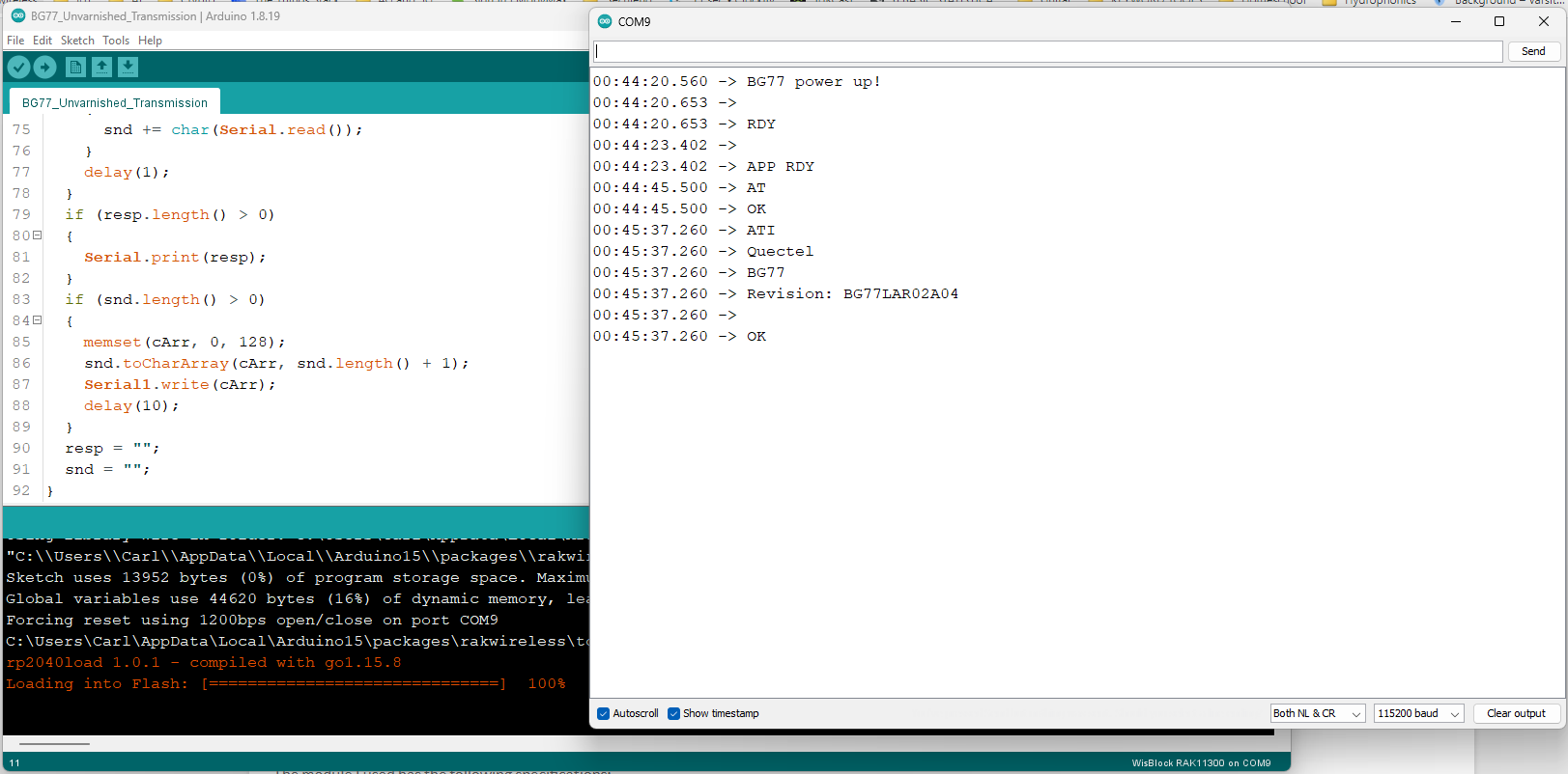
I’m using the BG77_Unvarnished_Transmission.ino sketch from the example repos to test. I get the response to the ATI command in the setup() section but no responses to anything typed at the terminal, including +++
[EDIT] If I replace the ATI in the sketch with AT&V this is the output:
11:25:46.087 -> BG77 AT CMD TEST!
11:25:47.495 -> Modem response after start:
11:25:47.495 -> AT&V

11:25:47.495 -> &C: 0
11:25:47.495 -> &D: 2
11:25:47.495 -> &F: 0
11:25:47.495 -> &W: 0
11:25:47.495 -> Q: 0
11:25:47.495 -> V: 1
11:25:47.495 -> X: 4
11:25:47.495 -> Z: 0
11:25:47.495 -> E: 1
11:25:47.495 -> S0: 0
11:25:47.495 -> S4: 10
11:25:47.495 -> S5: 8
11:25:47.495 -> S6: 2
11:25:47.495 -> S7: 0
11:25:47.495 -> S8: 2
11:25:47.495 -> S10: 15
11:25:47.495 -> S3: 13
11:25:47.495 ->
11:25:47.495 -> ERROR
11:25:47.495 ->
11:25:51.521 -> BG77 power up!
Hi @phil ,
I did some test on my RAK11310, I can validate that the module is responsive to AT commands.
Can you confirm if you have an external battery connected? Also did the RAK5860 Blue and Green LEDs turn on?
HI Carl. Yes to the battery, 18650 reading 4.2V. Blue LED is lit steadily and green one is flashing every 2 sec.
Hi @phil ,
It looks like that the device was successfully powered up. Were the modules working ok before in your specific application? Did you configure them in a certain setting that could probably cause the No Service return?
PS, I have no NB-IoT/LTE-M network in my location so I am only testing communication between the Core and Wireless Module.
I was successfully connecting to Hologram with three of them until last week. I’m about 15 km from the cell tower with signal levels averaging between -90 and -105 dBm, so I wanted to try to diagnose that further. I’ve done no configuration changes that should have caused this and have issued AT&F0 commands to each one of them to force them back to factory defaults.
Our application will be in rural locations, so we need robust performance at low signal strength. We are expecting to use antennas in most deployments, but I’m not reassured by the lack of stability I have experienced so far. I’m using an outdoor antenna for testing, BTW.
The stability question is why serial response is a blocking issue for me. Because of the shared serial port, I already have to figure out a way to turn off the UART RX every time I open the comms with the modem, because I need to interrogate it to find out whether the session is still up or needs to be reinitiated. This adds both hardware and software complexity to the application.
One more data point: Here is the reply if I query URC:
10:23:38.032 -> Modem response after start:
10:23:38.032 -> AT+qurccfg="urcport"

10:23:38.032 -> +QURCCFG: "urcport","usbmodem"
10:23:38.032 ->
10:23:38.032 -> OK
10:23:38.032 ->
10:23:42.070 -> BG77 power up!
Hi @phil ,
What do you mean with the shared serial port? Are there multiple connection to the UART lines?
Since I can confirm that the RAK11310 and RAK5860 works fine. Maybe the cause of non responsiveness is on some settings/configuration (HW or SW) of your setup or sequence of setup. Are those modules that stopped responding didn’t recover? Will you were able to communicate to it again? Either using Hologram or other NB-IoT/LTE-M SIM on your telco network?
I’m using the RX01 pin on the UART to get a TTL message stream from a controller device in the same housing. When I started testing the outbound communications, I realised that I would need to shut off this input temporarily so that I could read the response from the BG77. So I’ve been running with the line disconnected in order to observe the modem in isolation. All I get now is no service, and the only response is when I pass AT commands inside a sketch, as in the examples above.
Is it possible that we should be looking at the 11310 module for clues?
Generally, connecting multiple connections to UART lines is not advisable unless it was specially designed to sniff signals like logic analyzers (optimize to have a very high input impedance). But if it is working on your setup then probably it is ok.
The “No Service” is likely connected to the cellular operation of RAK5860’s BG77 Module and not the RAK11310.
I expect to need a switch in the path so that when I’m interrogating the modem I only see its responses. For now, I agree that the “No Service” is a signal related issue and that is why I was intending to look at it in real time by sending AT commands from the terminal.
When the modems were working, the typical signal strength displayed was in the range of -98 to -108 dBm. Now they are all showing “No service” and a Hologram SIM in my mobile phone says it is in service and gives a signal strength of -103 to -110 dBm.
I’ll carry on for the moment by embedding the AT commands in the Unvarnished_Transmission sketch and I’ve ordered some RAK11200 modules to build prototype units with wifi instead of cellular comms. But we will need the modems in production, so solving this is important.
Hi,
found this thread as I keep seeing the same exact issue, BG77 stops answering to any AT commands.
WisBlock RAK4631 + 5860 as the combination with BG77_Unvarnished_Transmission
Any progress since May 2023?
Hello @s93082
I am running a test right now. Some questions:
Thanks
Felix
Hello
Further digging into this issue is related to PSM/eDRX in "normal"operation case. If PSM and/or eDRX happened to be active BG77 stops responding to AT commands. This is fine and apparently forgot that this is how BG77 works.
Another issue is that RAK base board 19007 is not functional with the core 4631 + BG77 RAK5860.
Only the previous v1 base board RAK5005 seems to work just fine.
So, in short, all my (real) problems were due to this RAK base board 19007.
You need a battery for reliable function of the RAK5860
Hardware Setup
Reason is the high current consumption of the cellular chip. There might be a brown-out at any time and the Quectel chip is shutting down or malfunction. Specially while it tries to connect to a cellular network.
I see, any improvement in sight/planned? some cellular module that could be used instead of BG77?