Arduino on Rak5010!

Hi Everyone.
Since Micropython on Rak5010 published last week, more and more developers show great interest on it.
So we will publish Arduino on Rak5010 this week, it will be as popular as Micropython on Rak5010.

OK! Here we go!

  1. What is Arduino?
    If you know little about Arduino, please have a look below:
    https://www.arduino.cc/

  2. You have known Arduino. Install the IDE first:
    https://www.arduino.cc/en/Main/Software

  3. What lib is used?
    Rak5010 is based on nRF52840, so as Adafruit Feather nRF52840 Express. Therefore Arduino Core for Adafruit Bluefruit nRF52 Boards is suitable for Rak5010, except for the GPIO maping table. This makes it easily to transplant. Rak5010 use the lib of Adafruit and gpio maping of PCA10056.

  4. How to install Adafruit Bluefruit nRF52 in Arduino?
    https://github.com/adafruit/Adafruit_nRF52_Arduino

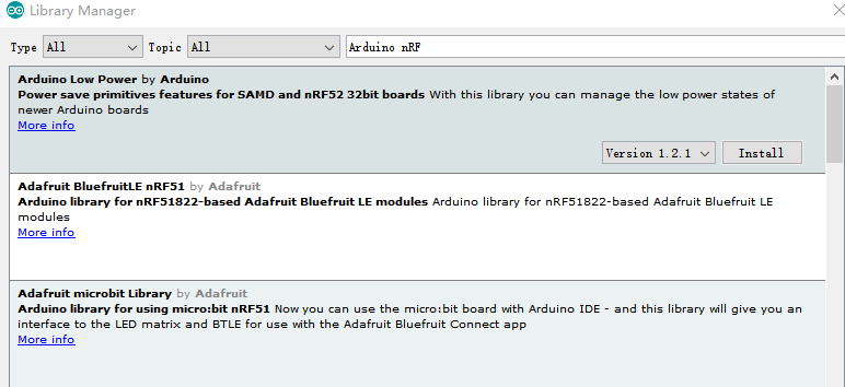
  5. Check the other lib below install or not?

  6. Download the gpio map of Rak5010 from:
    https://github.com/RAKWireless/Arduino-on-Rak5010-
    It contains gpio maping, serial tool, demo project and important hex.

  • PCA10056: GPIO maping of Rak5010

  • Serial tool: A good tool for debug

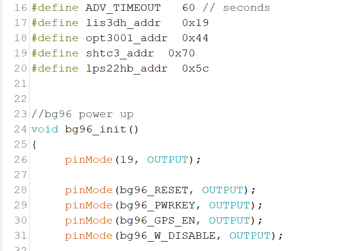
  • Rak5010.ino: Demo project

  • feather_nrf52840_express_bootloader-0.2.13_s140_6.1.1.hex : Hex include softdevice6.1.1 and bootloader support USB download from Arduino. It is a great method.

  1. Replace your code with our code PCA10056, your code path maybe like:
    C:\Program Files (x86)\Arduino\hardware\Adafruit\Adafruit_nRF52_Arduino\variants\pca10056

  2. OK, development environment is finished. The next step is very important. Download the hex to Rak5010 with Jlink. It just need once.

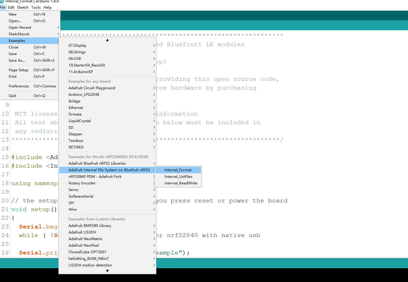
  3. Open the Rak5010.ino, connect Rak5010 to your pc via usb. It will be recognized as Adafruit Feather nRF52840 Express :slight_smile:.

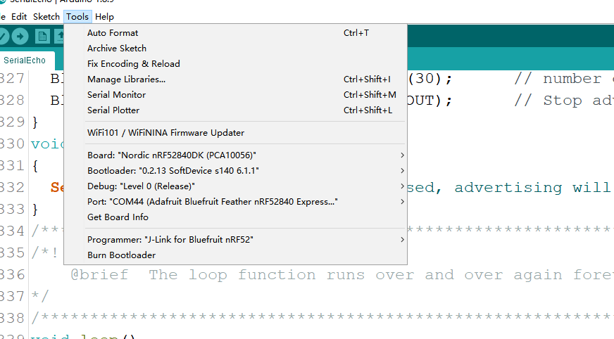
  4. Check the config, it should be like below:

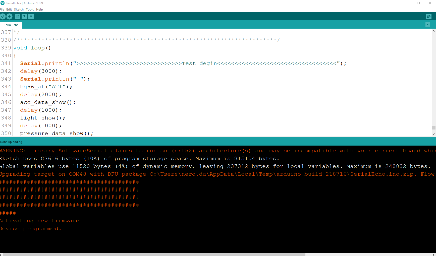
  5. Compile and download. Ingnore the Waring:

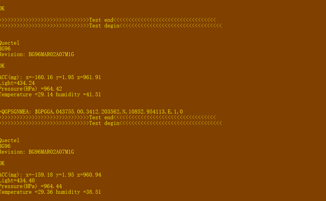
  6. When download ok. Remember to remove the usb, open serial tool, insert usb, The demo project shows all sensors data on Rak5010 and a ble advertiser named “Rak5010”.
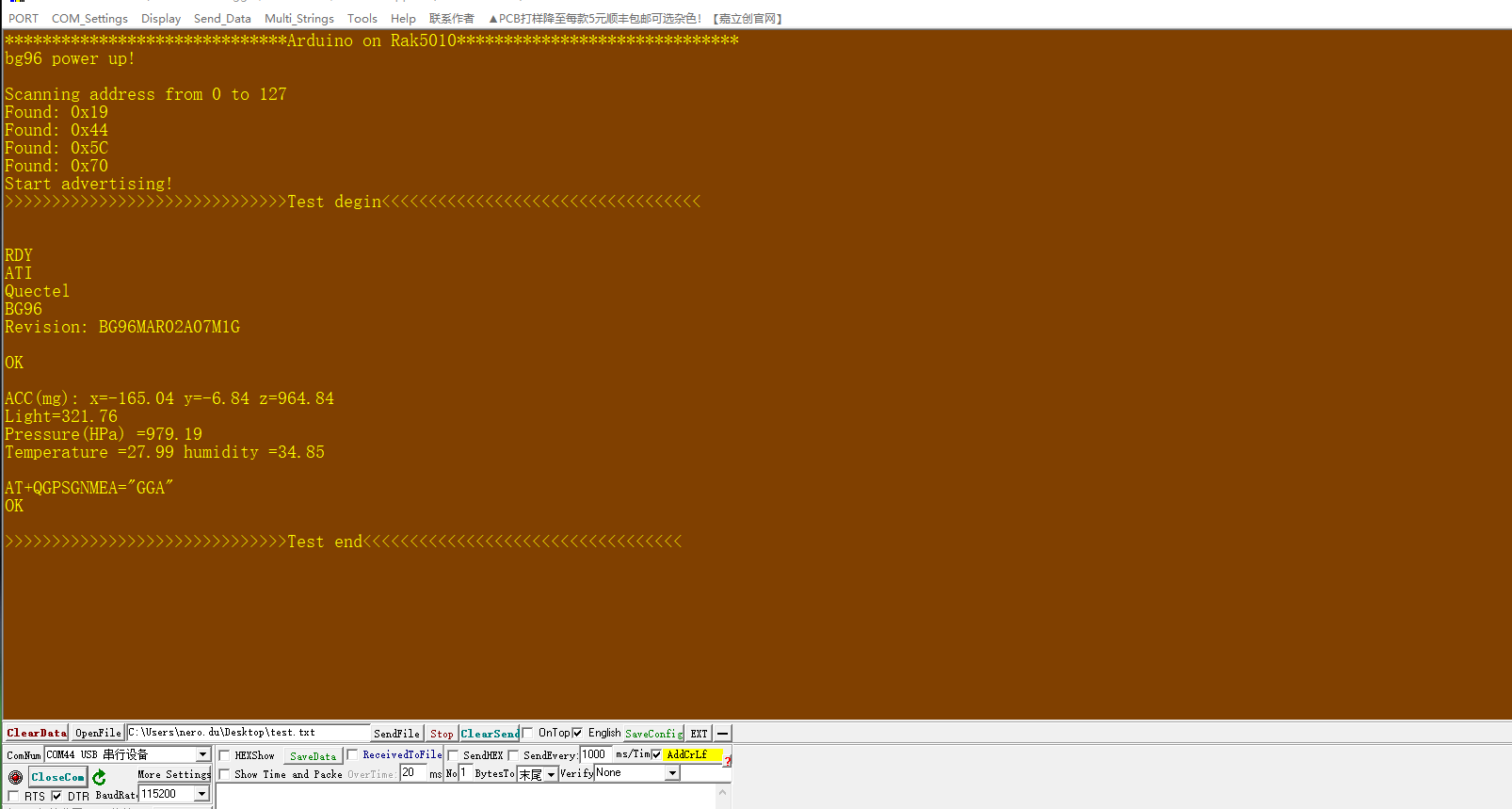
Notes:
The power up order is similar as power down order. So if download finish, change to serial tool directly, bg96 may power up fail. Secure order is:
Download—>remove usb(power down)—>insert usb—>open serial tool.

We have solve some bug, changelog is below:

  1. Add bg96 init about ATE0, GPS config just once

  2. Because the hardserial RX buffer size is limited for 64. Some AT response will show just part like GPS. It seems not a easy problem.

  3. If you write your code about communicating with bg96, remember each AT will need return info. It is better read it for clean the uart buffer. Do not just send without read.

1 Like

Hi Nero,

I’m testing out the RAK5010 with Arduino and it seems the GPIOs and the green user LED3 are missing in the variant.h file.

Or did I miss something? I would like to connect a tiny buzzer.

Could you also post an example of how to use the flash memory to store some variables please?

Thank you for your support.

Hi,
You are right. The LED3 is not in the header in this example.
If you want to connect peripheral, there are four gpio on the board.
As you know, it is based on adafruit bsp library, and the made a litttle file system in it. So I think you can refer these examples:

Thank you,

The Bluefruit FS is working with the examples.

Could you please tell me what are the digital GPIOs PIN numbers on the Arduino?

I would like to do a digitalWrite(BUZZER_PIN, HIGH)

Thanks

Hi,
You can refer to this:

There are 4 gpio for users. IO1-IO4, You can define it in variant.h with nordic pin num and use it. But remember to power up GPIO VREF which controls the 4 gpios on/off.

Hi Nero,

In the schematic the pin NRF_IO1 is the P0.19, but it seems to be already mapped in the variant.h as:
#define PIN_QSPI_SCK 19

I’m not confident enough to do that by myself, I worry to burn the circuit by doing a bad manipulation.

Could you please update the official RAK5010 Arduino support to add the GPIOs and the green LED?

That would help everyone else who want to use Arduino.

Thanks

Hi,
In fact, the gpio define in variant.h is what you decide. I used the I2C and uart, so I just change the relevant gpio. As for others, change to what you want. It will not have any problems because of 5010 not used others, like QSPI.

Sorry I really don’t understand how to do that, can you show an example on to map the GPIO and power up the GPIO VREF on Arduino please?

In fact, there is no need to do it in variant.h, you can do it directly in .ino like below:

The pin number is 19, just do directly. As for the VREF, it just needs external power 3.3 V. It can’t be pulled in code.

Thanks,

Can you please confirm that the VREF is the J12 EXT_VREF PIN defined in https://doc.rakwireless.com/datasheet/rakproducts/pin-definition ?

Would you recommend to connect the J10 VBAT to J12 EXT_VREF PIN to power the GPIO?

The buzzer needs full power to get 90db sound volume.

Yes, J10 VBAT to J12 EXT_VREF PIN is OK. But remember to connect your GND buzzer to GND of 5010.

Hi, I have a problem starting up the BG96 module. I think that the blue led should be always on, but the LED is blinking and the terminal is printing RDY as soon as the LED turns on. I think the module is rebooting.

Hi,
It is because of the power is not stable. If you just use usb for power, it maybe power up failly. So you’d better connect to a chargebale battery or keep usb voltage stable.

1 Like

Hi all.
Can you please tell me if the following procedure can be done?

  1. Get the last Adafruit feather_nrf52840_express_bootloader-0.3.2_s140_6.1.1.hex from https://github.com/adafruit/Adafruit_nRF52_Bootloader/releases/download/0.3.2/feather_nrf52840_express_bootloader-0.3.2_s140_6.1.1.hex

  2. Download it to the smartphone and burn it using BLE using “nRF Connect” as explained at:
    https://doc.rakwireless.com/rak5010-wistrio-nb-iot-tracker/upgrading-firmware-through-dfu-over-ble

  3. Use Arduino IDE to program the nRF as posted here.

Thanks

Hi,
DFU in step 2 is based on our RUI firmware. It can’t be mixed with Arduino because of two system. In fact, Arduino support DFU with Adafruit code and hex. If you want to do it, you can refer to the this. But remember, the board must have firmware support DFU. If empty, nothing can be done.

#include <Arduino.h>
#include <bluefruit.h>

// Forward declarations for functions
void connect_callback(uint16_t conn_handle);
void disconnect_callback(uint16_t conn_handle, uint8_t reason);

/**
@brief BLE DFU service
@note Used for DFU OTA upgrade
*/
BLEDfu bledfu;

/**
@brief Arduino setup function. Called once after power on or reset

*/
void setup()
{
// Initialize built in green LED
pinMode(LED_BUILTIN, OUTPUT);
digitalWrite(LED_BUILTIN, HIGH);

// Initialize Serial for debug output
Serial.begin(115200);

// Wait for USB Serial to be ready or terminal to be connected
time_t timeout = millis(); // Timeout in case the system runs on its own
// Waiting for Serial
while (!Serial)
{
if ((millis() - timeout) < 5000)
{
// Blink the LED to show that we are alive
delay(100);
digitalWrite(LED_BUILTIN, !digitalRead(LED_BUILTIN));
}
else
{
// Timeout while waiting for USB Serial
break;
}
}

// Config the peripheral connection with maximum bandwidth
// more SRAM required by SoftDevice
// Note: All config***() function must be called before begin()
Bluefruit.configPrphBandwidth(BANDWIDTH_MAX);
Bluefruit.configPrphConn(92, BLE_GAP_EVENT_LENGTH_MIN, 16, 16);

Bluefruit.begin(1, 0);
// Set max power. Accepted values are: -40, -30, -20, -16, -12, -8, -4, 0, 4
Bluefruit.setTxPower(4);
// Set the BLE device name
Bluefruit.setName(“RAK4631_OTA”);

Bluefruit.Periph.setConnectCallback(connect_callback);
Bluefruit.Periph.setDisconnectCallback(disconnect_callback);

// To be consistent OTA DFU should be added first if it exists
bledfu.begin();

// Set up and start advertising
// Advertising packet
Bluefruit.Advertising.addFlags(BLE_GAP_ADV_FLAGS_LE_ONLY_GENERAL_DISC_MODE);
Bluefruit.Advertising.addTxPower();
Bluefruit.Advertising.addName();

/* Start Advertising
- Enable auto advertising if disconnected
- Interval: fast mode = 20 ms, slow mode = 152.5 ms
- Timeout for fast mode is 30 seconds
- Start(timeout) with timeout = 0 will advertise forever (until connected)

 For recommended advertising interval
 https://developer.apple.com/library/content/qa/qa1931/_index.html

*/
Bluefruit.Advertising.restartOnDisconnect(true);
Bluefruit.Advertising.setInterval(32, 244); // in unit of 0.625 ms
Bluefruit.Advertising.setFastTimeout(30); // number of seconds in fast mode
Bluefruit.Advertising.start(0); // 0 = Don’t stop advertising after n seconds
}

/**
@brief Callback when client connects
@param conn_handle: Connection handle id
*/
void connect_callback(uint16_t conn_handle)
{
(void)conn_handle;
Serial.println(“BLE client connected”);
}

/**
@brief Callback invoked when a connection is dropped
@param conn_handle: connection handle id
@param reason: disconnect reason
*/
void disconnect_callback(uint16_t conn_handle, uint8_t reason)
{
(void)conn_handle;
(void)reason;

Serial.println(“BLE client disconnected”);
}

/**
@brief Arduino loop. Runs forever until power off or reset

*/
void loop()
{
}

Thanks Nero!.

In fact, my target is to use Arduino IDE to make my own code and burn/upload it using the USB connection to the computer.
Is there a way to reach this, without using Jlink (as stablished on 8 of first post)?

I have a new rak5010.

No matter what IDE, the board must have the initial hex. Empty flash can do nothing. Jlink or DAP link is necessary.

So. With initial hex can I flash the arduino hex using BLE?
And then use USB for next hex?

Yes. You need a application and DFU file. You can refer to

Install it and refer to the bluefruit ble example. They provide the example of DFU.