
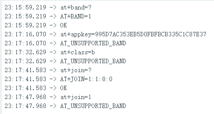
I am a student just learning to use the rak3172 evaluation board and I am having the following problem: Why does my RAK3172 always return AT_UNSUPPORTED_BAND when I assign it using at commands such as at+appkey=xxxx, at+class=b, but my BAND = 1 (CN470) is correct!
I would be very grateful if you could answer this as soon as possible, it would be very helpful in moving my experiment forward. Thanks!
Welcome to the forum @JoeyWayneCN
What RAK3172 do you have? There are different hardware versions
| Module | LoRaWAN regions |
|---|---|
| RAK3172 with IPEX 800MHz | EU868, RU864, IN865 |
| RAK3172 with IPEX 900MHz | US915, AU915, KR920, AS923-1/2/3/4 |
| RAK3172 with IPEX 900MHz | AS923-1 Japan |
| RAK3172 with IPEX 433MHz | EU433 |
| RAK3172 with IPEX 470MHz | CN470 |
Unless you bought the CN470 version, you cannot select this band.
Other possibility, if you bought the CN470 version, is that you connected something to GPIO PB12.
| Pad # | GPIO | Function | Remark |
|---|---|---|---|
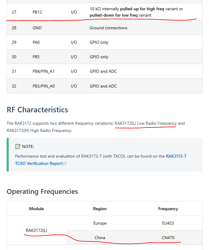
| 27 | PB12 | I/O | 10 kΩ internally pulled-up for high freq variant or pulled-down for low freq variant |
Thank you very much for your reply.
My rak3172 is indeed the CN470 version, but I didn’t do anything with the GPIO PB12 you mentioned.
I checked the documentation as in the picture, does it mean that I should pull down PB12 for low frequency ?
Could you please provide a link to the guide for doing this with the PB12?
You should not connect anything to this pin, it is connected internally.
Can you check on an open PB12 (pad 27) if it is pulled low or high? Measure resistance to GND and VDD.
Can you see on the label of the module somewhere a (L) printed?
I don’t have a device that I can use to measure resistance to GND and VDD.
RAK3172L-CN is printed on the label of the module.
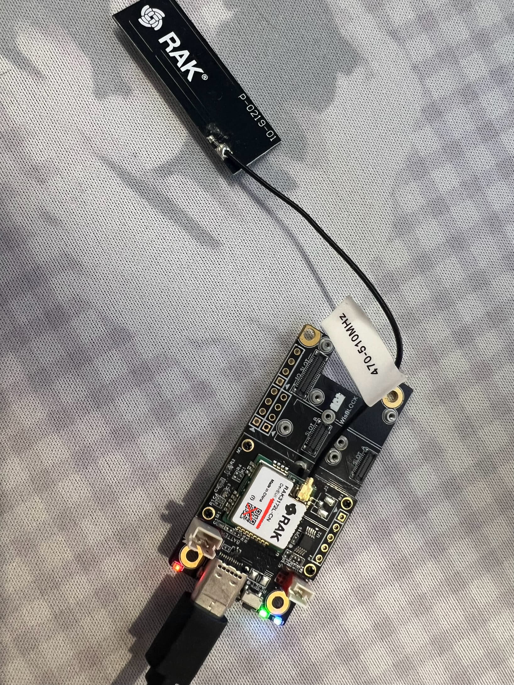
The label indicates that it is a RAK3172 for China.
Can you send the commands
AT+VER=?
AT+HWMODEL=?
AT+HWID=?
AT+BOOTVER=?
and send me the responses.
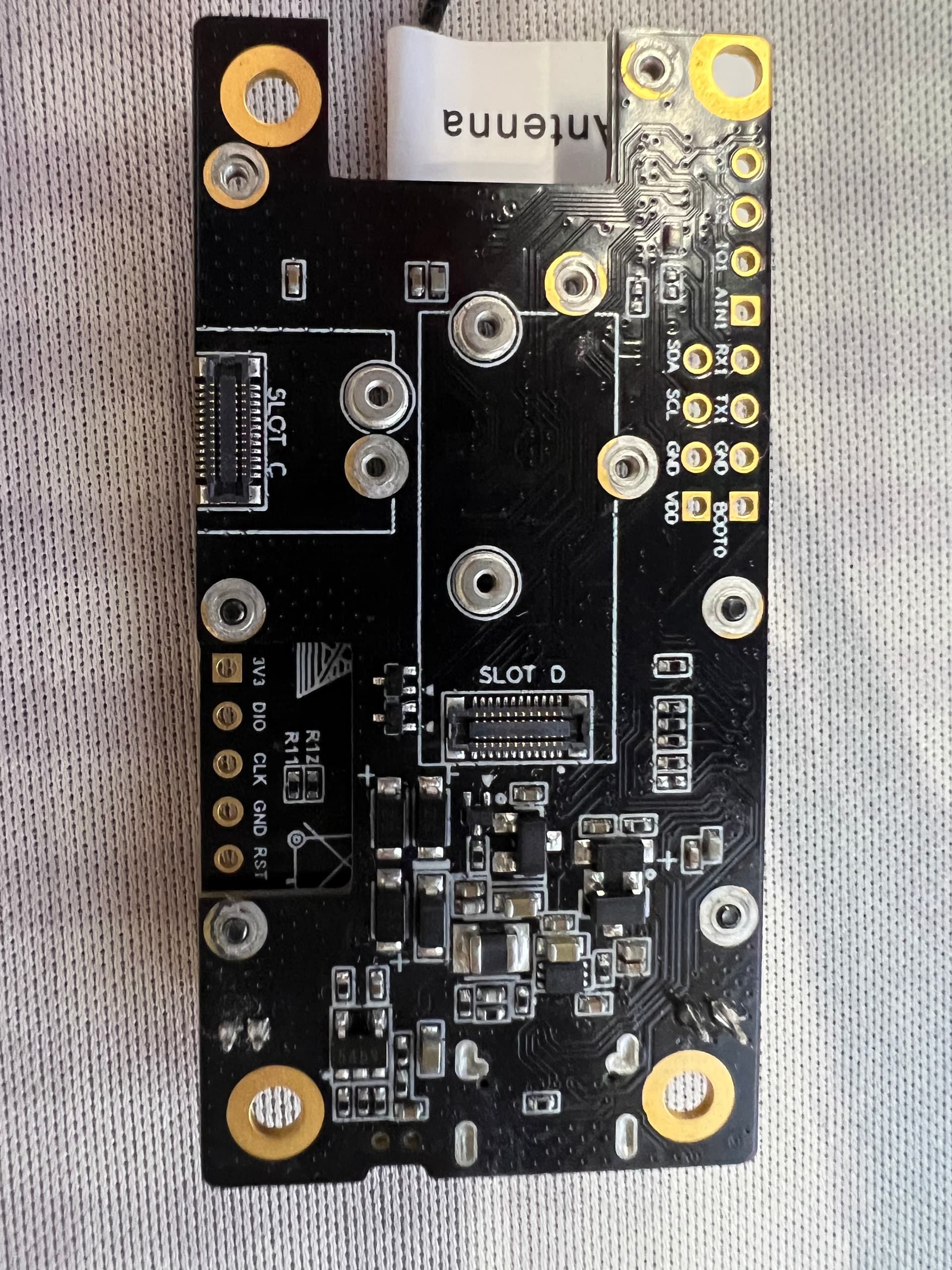
Do you have any WisBlock module in the Slot C on the bottom of the Base Board?
AT+VER=RUI_4.1.1_RAK3172-E
AT+HWMODEL=rak3172
AT+HWID=stm32wle5xx
AT+BOOTVER=RUI_BOOT_0.6_STM32WLE5CC
Slot c is shown in the picture.
Is this the default AT command firmware that came with the RAK3172?
Or is this a custom firmware you created with Arduino IDE?
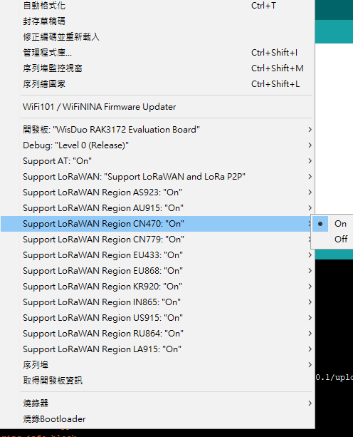
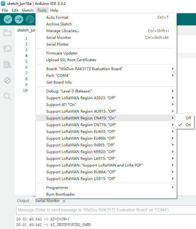
If custom, check that CN470 is enabled:
Can you share your code, maybe as direct message.
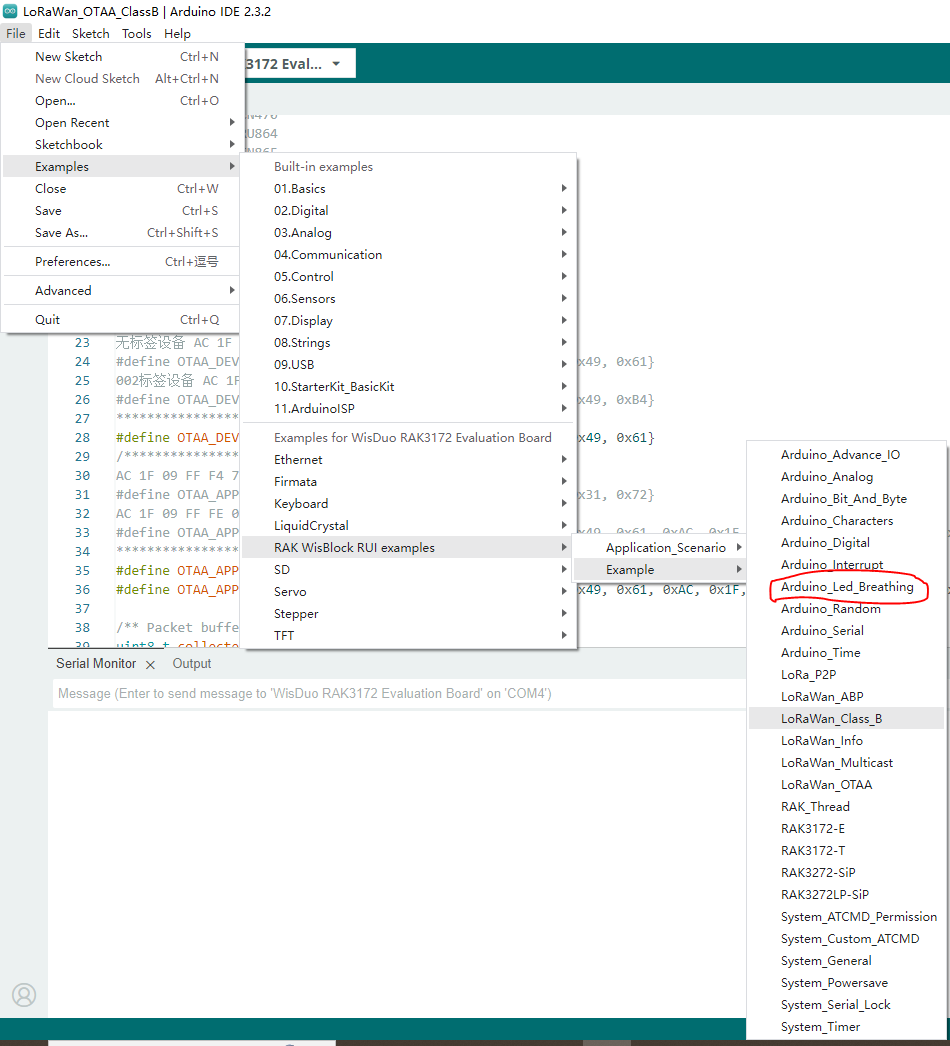
I have uploaded the examples code of Led_Breathing to my Board.
code:
/***
- This example shows led breathing by analog.
***/
#if defined(WISBLOCK_BASE_5005) || defined(WISBLOCK_BASE_5005_O)
uint8_t ledPin1 = LED_GREEN;
uint8_t ledPin2 = LED_BLUE;
#else
#warning please set the right pin refer to the documentation.
uint8_t ledPin1 = 0xFF;
uint8_t ledPin2 = 0xFF;
#endif
int val = 0; // variable for LED brightness value
bool state = false; // variable for control led brightness status
bool ledSwitch = false; // variable for switch led
void valChage()
{
state = !state; // invert led control brightness status
if (val == 0)
ledSwitch = !ledSwitch; // switch led when one of the led is darkest
}
void setup()
{
//initialize serial communcation at 115200 bits per second
Serial.begin(115200);
delay(2000);
Serial.println("RAKwireless Arduino LED Breathing Example");
Serial.println("------------------------------------------------------");
// initialize the LED pin as an output
pinMode(ledPin1, OUTPUT);
pinMode(ledPin2, OUTPUT);
}
void loop()
{
// call function when led is brightest or darkest
if (val == 0 || val == 255)
valChage();
// determine to make the led lighter or darker
if (state)
    val++;
else
    val--;
// To switch the lighting led
if (ledSwitch)
    analogWrite(ledPin1, val);	// Light the green led
else
    analogWrite(ledPin2, val);	// Light the blue led
}
After enabled, I uploaded the code again just now. The at command work now! Thanks for your patient replies!
You’re welcome.
Let us know if you have further questions.