Hello guys,
i need help with the following scenario:
i would like to hook up a RAK3172 that will be running with a 3.6v battery to a hall effect cable coming from a water meter, and use interrupt to detect the pulse. the system will be sleeping until an interrupt happens then it’ll wake up register the count and goes back to sleep.
my questions are purely hardware related:
Should i hook up one end of the cable to PA8 and the other to 3.3V or GND, which is more energy efficient ( Pull up or Pull down)
Assuming i hook up one end of the cable to 3.3v then should i use the internal pulldown or keep the pin floating and use an external resistor to pull it down with GND? if yes what value?
if used the internal pulldown, and the meter is running slow, and keep the hall effect engaged it will draw a lots of power while that state (PIN Connected to 3.3V) and the pin is pulled high, so how to i fix this so the current it will be drawing will be in ua while guaranteeing an interrupt? should i use a 1M ohm between the PIN (PA8) and GND? or what value should be best?
to avoid false interrupts (noise in the line or external interference) should i use a resistor in series with the cable end hook up to pin PA8 ? if yes what value is best, 10K or more? or is that not necessary in this case?
Pull up or pull down really doesn’t matter as long as the switch is not engage most of the time. If you just switch it very quick, difference is unnoticeable.
Internal pull ups and pull down are commonly called weak. You can secure the integrity of the signal by having an external one. There is no general rule on the value though common resistors like 10k are used to have multiple same components on board. In terms of signal quality, the lower the better but with the trade-off of power consumption.
I do not understand this part. When is the switch activated and deactivated? What is the duty cycle and period?
How long is the cable? If it is too long, then it will not be just a simple wire but will exhibit parasitics (capacitance and inductance). It can even behave as antenna. Series resistor might help damp any potential ringing? I think 10k is too much. If you have 10k pullup or pulldown, your signal will be half already.
That’s the thing, the water meter is a big diameter one and the dial turns very slow and sometimes keeps the switch engaged for a longtime so it makes a huge difference as in this state without any external resistors the consumed current is high in mA. so i tried a 1M ohm between the PIN and GND and the power consumption while the switch is engaged went down to uA. so is this OK ?
so i should either use Weak pull ups/downs or external one ?
this situation is explained in one when the Water meter dial turns very quick no problems, but when it turn slow the switch stays engaged and draws current. And if the water meter stops at this state then the current continues to draw until it moves and open the switch.
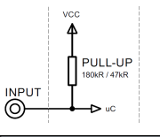
the cable is about 1 meter long, i have all size resistors available and was wondering which size is more appropriate… i read somewhere that some LoRaWan device use 180K for water meters and 47k for gas (see snapshot below) but didn’t understand the science behind it so hence why i asked here.
I do not work as a hardware design now so maybe not the best resource on this topic. Still I will share to you what I think can be helpful.
Values of pull-up and pull-down resistor will depend on input characteristic of the pin like its input impedance. 1M ohm resistor might be too high but if you do it in the field, you might see that it works fine. Some theoretical considerations and good read here - The Pull-Up Resistor: How It Works and Choosing a Value and https://www.electrical4u.com/pull-down-resistor/. When I still work as a hardware engineer, our team did tricks out of the book just to meet requirements (as long as approved by the management). We are just confident it works because we’ve tested it a lot like extreme power and thermal cycle, thermal shock, EMC susceptibility, short test, undervoltage, overvoltage, etc. 1M ohm seems big but who knows? It might work fine
If you will use 1M ohm external one, then it wont give any benefit resistance wise. Internal pull ups are somewhere around 47k to 100k.
Hmm. I have no experience with water meters. I have tried a LoRaWAN water meter before but it uses the optical output from the meter. I am not sure if your approach is the most optimal one.
That diagram is a pullup and not a series resistor. 1 meter is not that long. We have a setup before at 2 meter cable that failed EMC test, in our surprise, twisting the cable helps. It is a blackbox to me, but we just twist long cable (if possible) after we that experience. Case might be different on differential lines since those are floating or those shielded cable.
Thank you @carlrowan for the explanation, can you please point as to where i can find out the internal impedance of the pins on RK3172?
also the cable coming out of the water meter is indeed two meters long and not one, so yes it does sometimes act like an antenna and trips the pin.