Hello, I have been trying to flash two RAK3172 modules using UART and ST-LINK. I use STM32CubeIDE for programming. Then I use STM32CubeProgrammer to flash RAK3172 in the following situations:
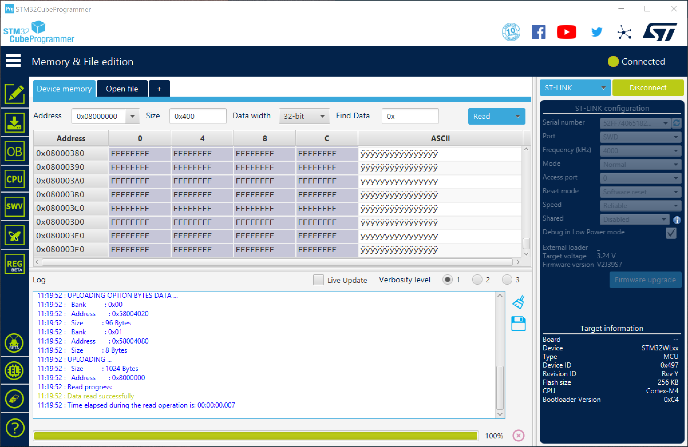
For flashing the module using UART, I can load the program to the module successfully when BOOT0 is connected to 3.3V. However, when I read the MCU to verify the code, it’s not the same. I can’t perform full chip erase (I can do this successfully with my WL55 KIT in the same setup).
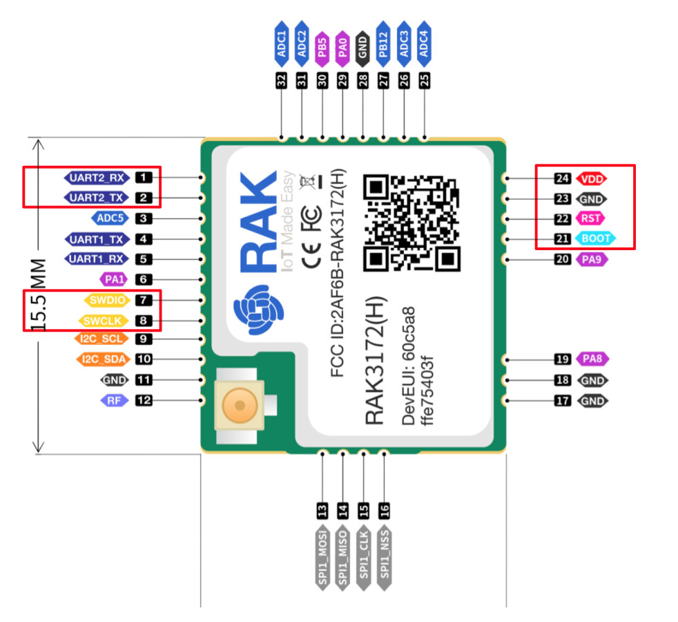
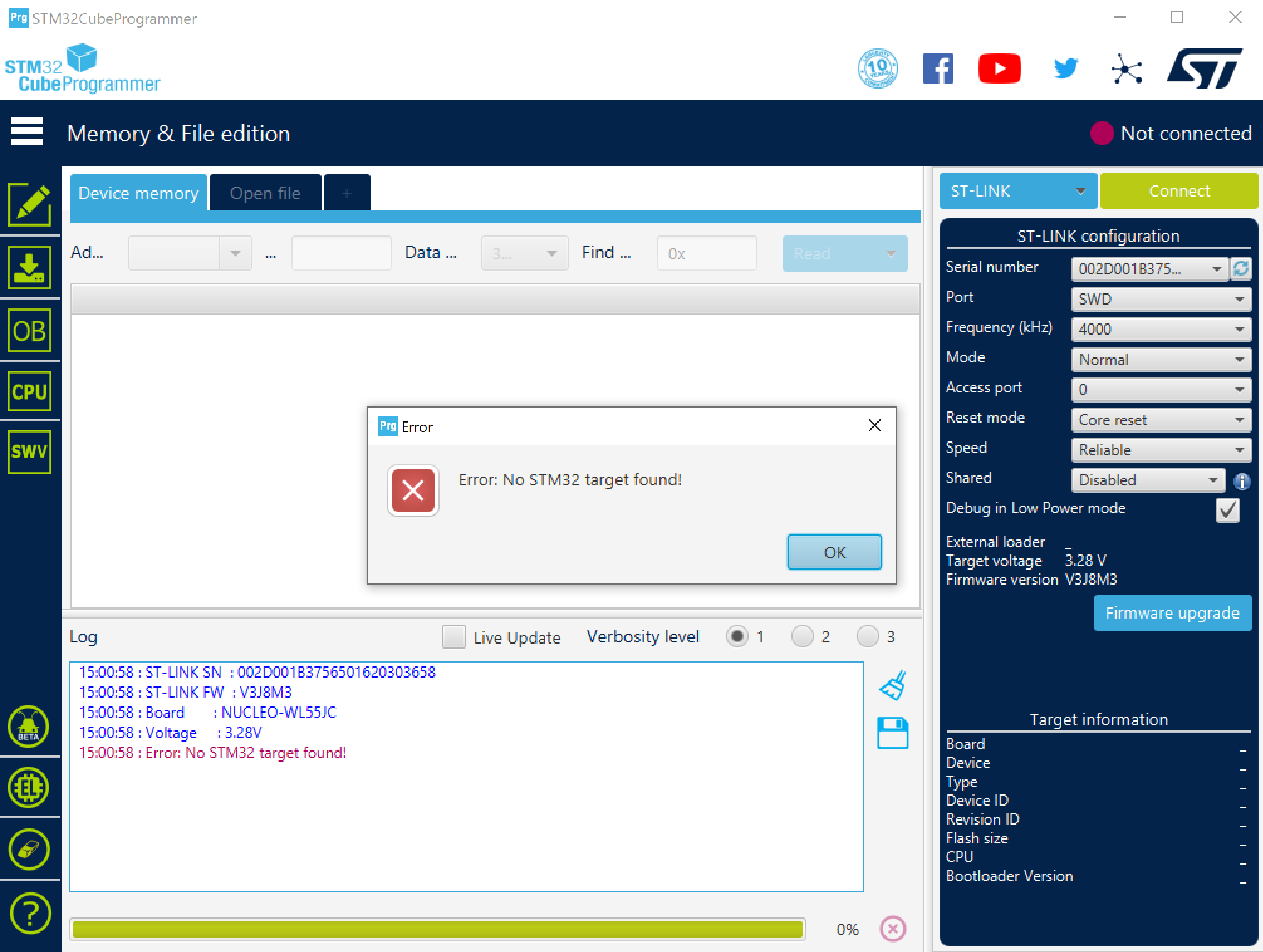
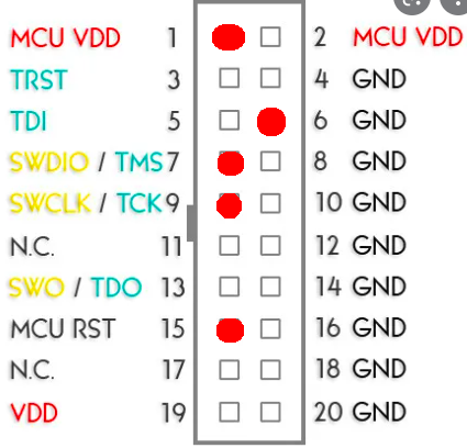
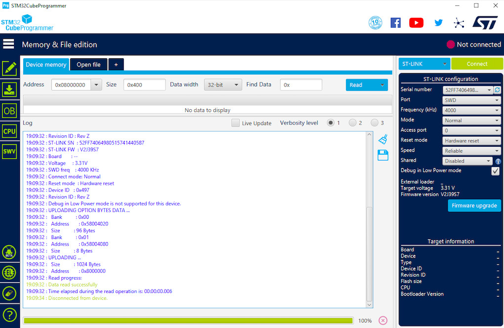
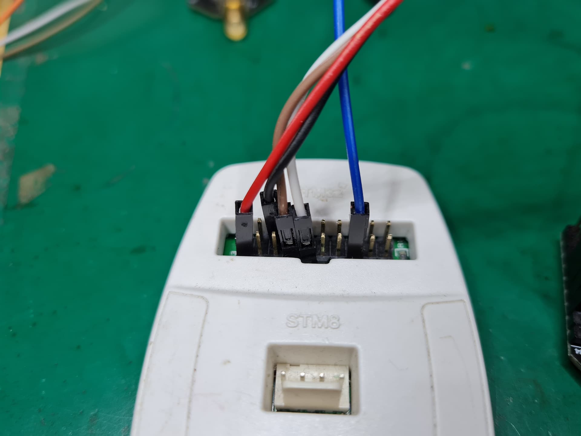
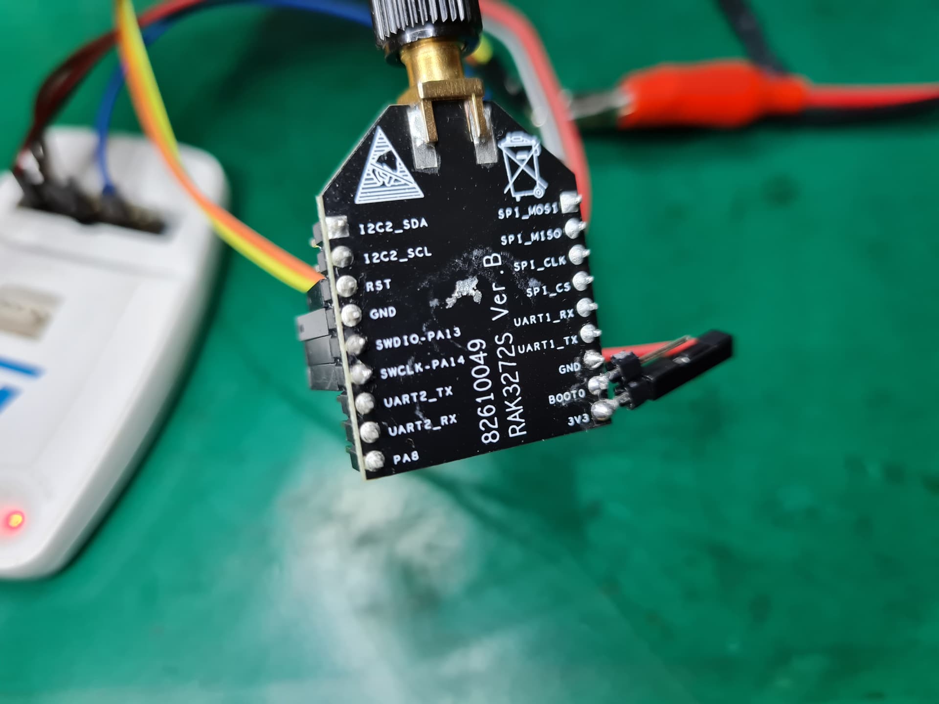
When flashing two separate RAK3172 modules using ST-Link debuggers (I used both ST-Link V2 and V3), I got no response, no STM32 target found when I connected BOOT0 to GND or 3.3V (conventionally connected to GND). I tried with all possible configurations on STM32CubeProgrammer: Port SWD, frequency varies from 950k to 12000kHz, mode normal or under reset, reset mode hardware or software, with reset pin connected or disconnected. I even opened up one module to check the connect between SW pins and the MCU, and everything seems correct. I used these pins during the test:
For UART, I reset the module after connecting BOOT0 to VDD, the program was loaded 100% successfully. But I can’t erase the chip in the same section.
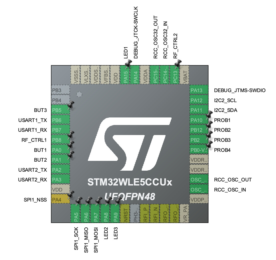
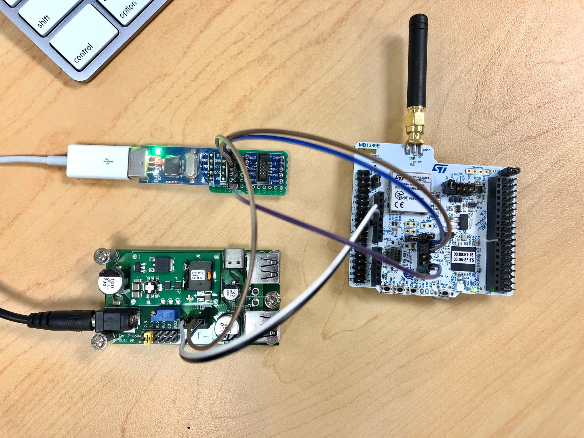
I connected the MCU to ST-LINK with SWDIO to pin 7, SWCLK to pin 8, and/or NRST to pin 22 using both ST-LINK V2 or V3. I connected 3.3V power supply from my WL55 KIT to the module. I measured VDD on the module and it’s 3.3V. I tried with unconnected BOOT0 and/or RST but no hope. I also got error when I use core reset mode:
Can you use a scope to see if there’s activity on the SWD lines when you make these attempts?
Also to see if the NRST line is actually driven when you command that?
Can you show exactly which pins you are taking the signals from on the STLINK’s header? If you’re using one of the common dongle form ones, notes that those are actually fakes, many of which don’t drive the reset line when commanded to.
Hi Chris, thank you for the insight. I used ST-LINK V3 in my STM32 WL55 board. I did the same thing with the Lora SoC WL55 on-board and it works even when NRST is not connected to the debugger.
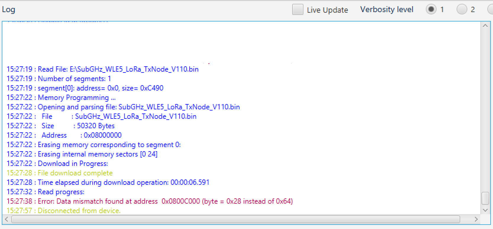
When I flash RAK3172 using UART. I can download the bin or elf file into the module. But always got error data mismatch when verifying, and the program doesn’t work after I tied BOOT0 to GND and reset the module:
Can you try to upload our .hex firmware if it will succeed in verification RAKwireless Downloads? If it does, then the issue is from your compiled FW.
For STLINK
I haven’t tried using the onboard STLINK of the STM32WL Discovery Kit. I have an original STLINK V2 and it works fine.
I am not sure if the on-board STLINK can be used externally for different STM32 MCUs. I believe it must be. But I am wondering in your image, it shows Board :NUCLEO-WL55JC.
Please show a detailed picture of how you have made the connections.
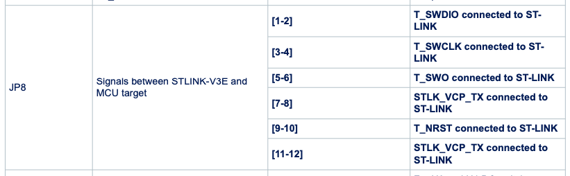
You need to both open the jumpers that break connection to the on-board target, and pick up the necessary signals to drive an external one.
Also, while distinct from achieving SWD access I believe it’s been determined that even single core firmware built for the WL55 won’t work on the RAK module due to its boot mode, unless you reconfigure the memory mapping or change the vector table address register to point to the actual address of flash at 0x08000000 rather than the alias at address 0 which points instead to the boot ROM.
Thank you. The hex file was loaded and verified correctly. The module works very well with your firmware. I can use AT commands to communicate with the module. Besides, I can flash my program into the module and run it now. But it’s impossible to debug my program using UART.
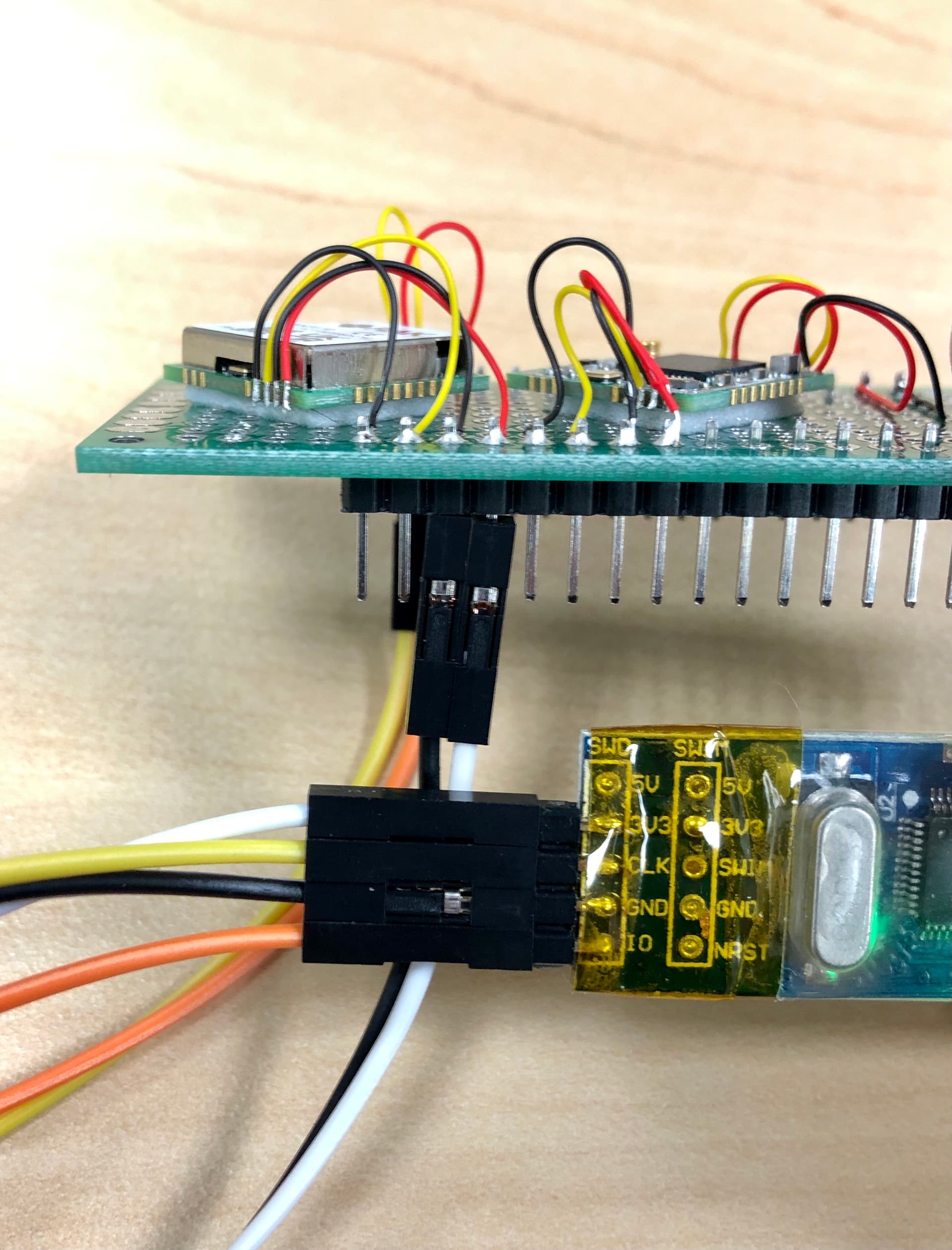
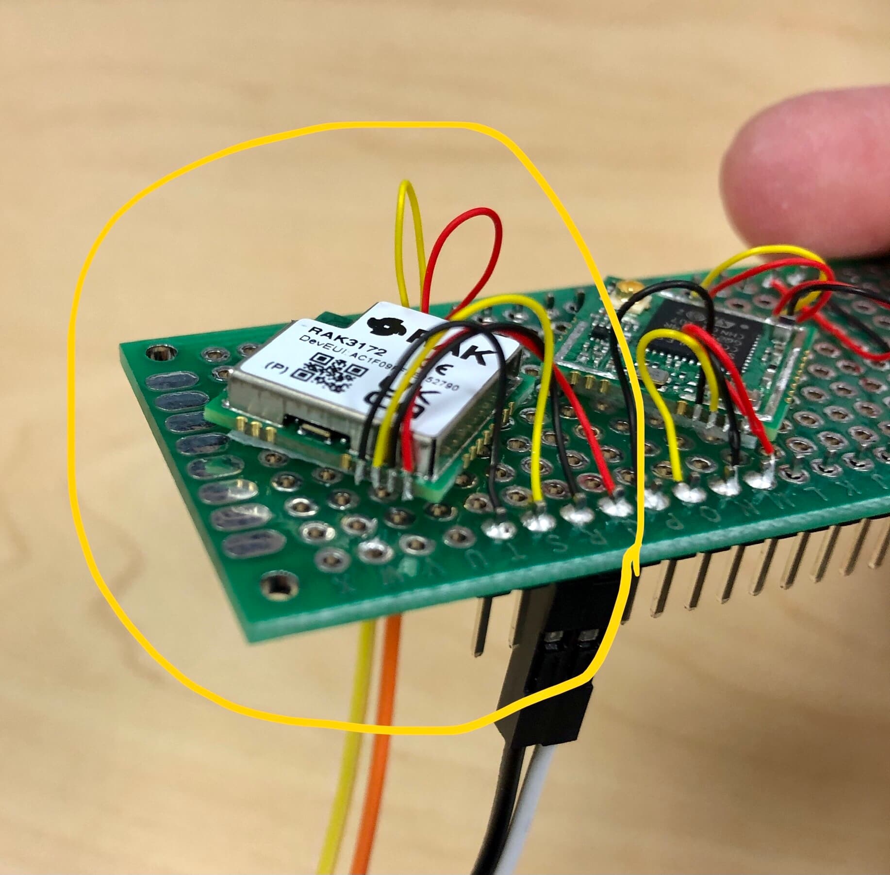
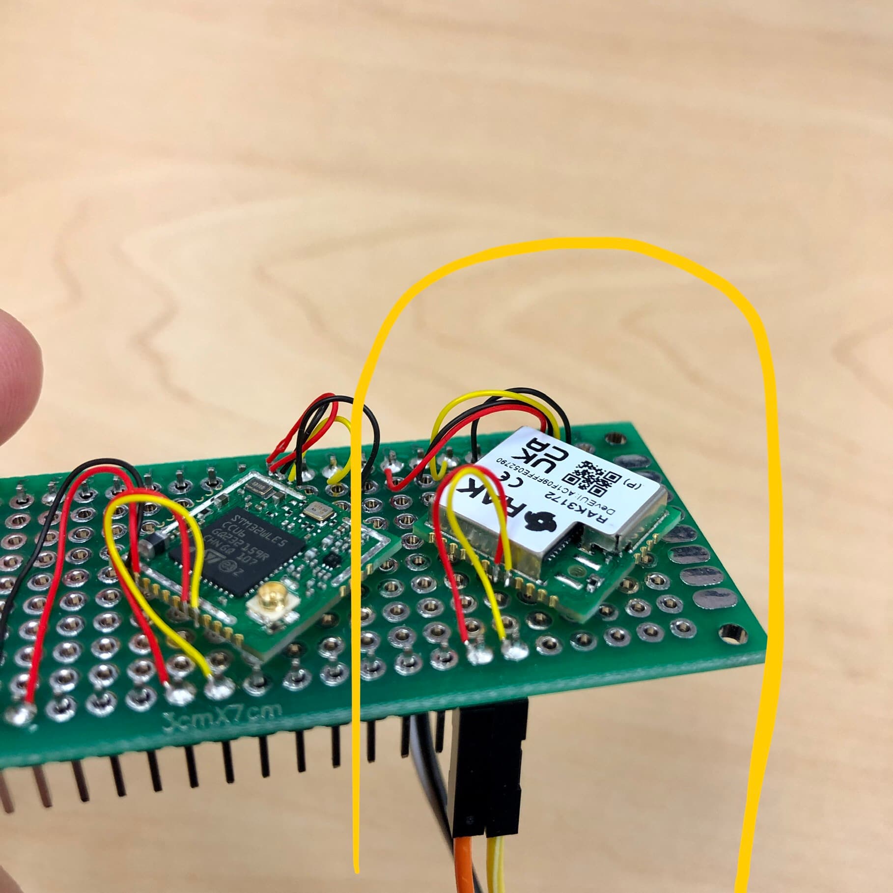
I created CubeIDE program from a WLE5 .ioc file (CubeMX), and generated the program files from that. I don’t use any files from WL55 for RAK3172. My ST-LINK-V2 works fine with STM32 F4 as well as WL55 SoC. This is my connection between ST-LINK-V2 and RAK3172, please check it out:
Thanks Chris, yes I understand that. I always disconnect the jumpers as showed below. It works for other STM32 MCUs but doesn’t work for my two RAK3172 modules.
I am not sure how you can use the on-board ST-LINK of STM32WL DK since it doesn’t have the MCU Reset pin for Hardware Reset mode. It only has T_NRST which is used for JTAG.
I have experience before that STM32CubeProgrammer can’t detect the chip using STLINK. But when I used STM32CubeIDE, it can successfully debug and run projects using the same STLINK and connections.
It seems that the STM32CubeIDE has its own STM32CubeProgrammer in it.
Thank you so much for the support. I tried again using ST-Link-V2 connected to WL55 SoC. I have a NRST pin on my ST-Link-V2, and I can read the MCU only when NRST is connected to the SoC’s RST. So I think T_NRST and MCU_RST are the same. The connection and the result for my ST-Link-V2 and the SoC with external power supply are showed below.
For RAK3172, I did exactly what you said using the same connection, but still no target MCU detected. When I try to do full chip erase using UART, it showed error and said to check for chip protection (this doesn’t happen with WL55 SoC using UART boot mode). But I couldn’t read any useful information using UART. I think something is wrong with the boot memory. I’m looking for STM32WL5CCU6 for swapping out the IC but it’s out of stock everywhere. I’m wondering if RAK has any RAK3172 modules without flashing the firmware in stock. I would like to purchase them right away.
What’s interesting about the bootloader verification issue is that the verify error seems to occur at the start the last flash page aka sector being written.
Your program was 50320 bytes long, which requires 25 2K pages or sectors. And the tool claims it erased sectors 0 through 24, hopefully inclusive.
But the error comes at the first word of sector 24.
If through some logic error (< vs <=), actually only 24 sectors (0 through 23) were being erased that would explain it exactly.
Can you concatenate 2K of arbitrary padding onto the end of your bin file and see if you push the verify error beyond 0x0800c490 such that your entire actual program gets loaded?
It’s not entirely clear to me if you’re dealing with ST’s ROM bootloader (most likely if your application can start at the start of physical flash) or a RAK bootloader, and if the tool you are using is ST’s or RAKs. I believe there are a variety of open source 3rd party tools that can drive the ST bootloader.