I’m using RAK4631 with the RAK19007 base board. On the baseboards datasheet, the IO2 is actually defined as pin 30 for the J1 connector.
The RAK4631’s connector diagram also shows pin 30 to point to IO2.
So - what am i not getting right about the variant.h file?
Which PIN should i set to LOW to disable the 3V3_S output for the various slots available? (i’d like to turn of some sensors completely)
I must be daft or stupid, but how does GPIO1.02 translate to 34?
Like, is there a translation table, or some special calculation?
Anyway, do i understand correctly that if i have a module on slot A and slot D, that i can turn on/off the 3v3_s by setting WB_IO2 to LOW/HIGH?
Is there a way to do that /per/ slot?
I’m currently using the RAK12014 on Slot A and RAK12500 on Slot D.
The device is meant to take a measurement and GPS fix and then send it out over Lora. The logic works, but i was optimizing this a little bit, by waking up the RAK12500 and then doing a distance measurement (while the RAK12500 was busy getting a fix).
The procedure for the RAK12014 uses the sensor.VL53L0X_Off() and sensor.end() when it’s done measuring. These two methods turn set WB_IO2 to LOW and change the WB_IO2 to INPUT.
This influences the GPS because i think the WB_IO2 also controls the power to Slot D.
This is not terribly clear on the datasheets of the RAK19007:
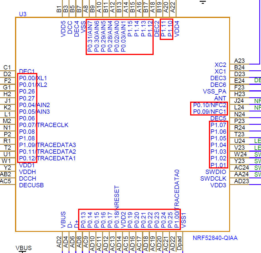
As Arduino cannot work with 0.01 or 1.12, the GPIO’s are just numbered like
0.00 => 0
0.01 => 1
…
0.31 => 31
1.00 => 32
1.01 => 33
1.02 => 34
…
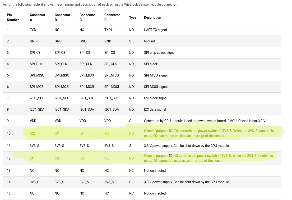
Each sensor slot has two supply pins called 3V3 (sometimes called Vdd) and 3V3_S.
WB_IO2 controls the supply voltage called 3V3_S.
WB_IO2 = high ==> 3V3_S is on
WB_IO2 = low ==> 3V3_S is off
Now it depends on the module if it uses 3V3 (Vdd) or 3V3_S as supply voltage. Modules that use 3V3_S can be switched off, modules that use 3V3 cannot be switched off.
The RAK12500 is using 3V3_S and can therefor complete powered down, controlled by WB_IO2.
You cannot turn off power of specific slots, you can only turn off 3V3_S and all modules that use it will be shut down.
I’m having trouble reading all the technical diagrams, that’s clearly due to my lack of knowledge… but - how would i be able to tell which pin is connected to what so that i know what i can set low/high? Do i have to trace the pins from the RAK4630 to the RAK4631 to the base board and then to the RAK12500?
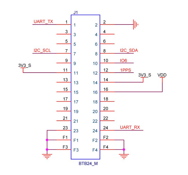
From what i understand, only the UART_RX can be used.
Why i get to that conclusion is this:
On the RAK12500 connector, we have these connections:
This would mean that only the following connections are connected:
UART_TX
I2C_SCL
I2C_SSDA
IO6
1PPS
3V3_S
VDD
UART_RX
As i’m using I2C to communicate, it means i can’t use VAL_RXM_PMREQ_WAKEUPSOURCE_SPICS.
The VAL_RXM_PMREQ_WAKEUPSOURCE_EXTINT0 and VAL_RXM_PMREQ_WAKEUPSOURCE_EXTINT1 don’t seem to be connected, which leaves only the UART_RX to use.