After using a different power supply it worked well ( no TX_TIMEOUT anymore) but not for very long.
Learning so far.
its not the GW
its not the hardware (may be the power supply)
its not in the code as such but may be in the boot loader etc)
Now I connected the 3172 dev board to an OTII battery analyzer to see the power draw and I can see that the chip never tries to send out something, so the error message makes sense. The problem is that something holds back the code to start sending.
Now I did the following test.
(1)
I flashed the complete firmware RAK3172-E_latest.hex ( fw 4.0.1. + bootloader) and test the TX using AT commands ( works - no error message, see the packets in the gateway, see power draw going up)
(2)
I reflashed your RAK3172-E_latest.bin using your DFU tool and did the same test - works!
(3) I flash a very simple sketch using 4.0.1 without even touching the LORA part in the code. I creates the .bin file and used DFU tool to flash not the Arduino IDE!
void setup() { Serial.begin(115200); }
void loop() {api.system.sleep.all(100000);}
I run the sketch but don’t use any AT commands.
(4) No I redo step two and flash your RAK3172-E_latest.bin. Test with AT commands fails ( no packet in Gateway, no power consumption increase indicating TX but the known error message: +EVT:JOIN_FAILED_TX_TIMEOUT
This means the very same firmware on the very same hardware does not work anymore once a compiled firmware that is not doing anything was flashed and started between. I repeated this pattern two times to make sure its really repeatable.
From this, I would conclude that the compiled sketch does something in some part of the flash that sometimes causes the problem.
To come closer to the root cause I need your help.
I there any portion of the flash that is written by the bootloader of a compiled sketch that I can compare?
If my understanding is correct, you suspect that there is a conflict on the .bin files of step2 and step3. When step3 doesn’t work, re-uploading step2 bin file will not work caused by bin file in step3.
Were you able to successfully connect the step3? As far as, I know, this the issue on the part 1 thread and the conclusion is voltage supply related.
On step3, when you mentioned LORA part in the code, is it still the LoRaWAN OTAA? Or LoRa P2P?
I am deeply convinced that having same hardware, same memory content and same environment a MCU will do the same thing. I am using same hardware and ( highly likely) same environment so it comes down to changed memory.
That’s why I flashed the standard firmware, checked the function, uploaded the compiled file, and then the standard firmware again. Since the AT commands don’t work after this process mentioned above I need to conclude that flashing and running the compiled code causes some change somewhere in the flash. This is further validated. When I flash the complete .hex firmware which overwrites additional parts of the FLASH the device works again ( works → AT commend cause a packet so send out).
After flashing the compiled firmware I do nothing except booting the MCU ( no AT commands at all).
From all this experience there is the most obvious explanation that something goes wrong during flashing or running the compiled firmware. I don’t think the flashing of the code goes wrong since the firmware works as such. its just not sending anything out.
I did further tests: Running the hardware with 3.0, 3.3 and 3.6 V - same result. Flashing from a PC and a MAC - same result.
So again, knowing either
(a) which flash parts are overwritten when FW update is done using your DFU tool or
(b) which flash parts are used for status variables by the firmware.
When using the generated .bin file by Arduino IDE either directly or using wistoolbox, it will only overwrite the application code section on the flash. The bootloader will be intact and unchanged. In your Arduino compiled code, if you change the OTAA parameters you previously set via AT commands, it will be overwritten too.
I did some test based on your sequence.
Flashed latest RUI3 firmware hex (4.0.1) via STM32CubeProgrammer. Tested AT command. And works.
Compiled LoRaWAN_OTAA example to generate the .bin file then uploaded via WisToolBox. Successfully upload and AT commands still works.
Uploaded the latest RUI3 firmware .bin file (4.0.1) via WisToolBox. Tested to TTN and I am able to connect/join successfully and send uplinks.
repeat steps 2 and 3 but still I get successful connection to TTN and send uplinks.
This test ensure that uploading .bin files generated by Arduino compilation or the default .bin file is ok. But take note that on each test, I have to make sure the that OTAA parameters are correct to join successfully. For example, if the DEVEUI you set in Arduino Code (step#2) is different on the DEVEUI you set via AT command in (step#3), the one that will be used is the latest written to the module.
I did the tests as I wrote in my post and ff course, I set the Keys before I trying the JOIN and yes, I have seen the very same bin working before too. The point is that it does not always work and I have a repeatable scenario where it does not work. Playing as long as it works and be happy is not an option. I need to understand what is the root cause and you should also have a benefit because the reason for this failure - whatever it is - will appear again; not always but sometimes as I have seen in other posts.
For this, I would spend more of my time looking into it since I understand your can’t repeat the same scenario I have here. My next step is to investigate what is different in the FLASH. I dont think the problem occurs during the flashing of the file but likely when it starts booting the first time - however, this is just gut feeling, no proof for it yet.
E.G. I see that after initial flashing the bytes at flash offset 0x4000 change ( this area is overwritten and initialized by the .hex file):
OLD (after .hex) 5a5a5a5a 00000000 08000139 00000000
NEW (after .bin) 5a5a5a5a 02020202 FFFFFFFF FFFFFFFF
Is this relevant? I don’t know. You guys know it for sure. That’s why I need the info I wrote so that I can continue to hunt down the problem. If you can’t give me the info, please let me know so that we don’t waste each other’s time.
Our team really look carefully on the different feedback I have to check with the team the memory locations. But surely some values in flash will change as new .bin is uploaded. On this scenario where flash offset 0x4000 was changed by the bin file, did the issue occur? Also for sanity check, whenever a device wont be able to join, common reasons (SW related) are not same euis/key, wrong band/masks, sometimes join delay settings and mismatch frame counter (these issues can occur on firmware level which we cannot negate). For the HW related ones: could be antenna, power supply, etc. If it is fw related, one way or another we will find out a repeatable pattern why the issue occur. This will be really helpful to find the fix.
The changes on the 0x4000 are not relevant as far as I can say. Meanwhile I make plenty of memory dumps and at least I can say: same memory causes same result. The problem comes down that every *.bin file self-compiled (either on MAC or on PC, with different voltages, with different UART connectors, different source code, …) shows the very same result: TX_TIMEOUT. Whenever I go back to your latest firmware published I have a working memory content. Of course, there are plenty of changes with self-compiled firmware so I can’t pinpoint where the problem really is.
Is there a source code of the firmware that you publish as latest https://downloads.rakwireless.com/RUI/RUI3/Image/RAK3172-E_latest.bin. ? This would help to do the next step.
Also having a compiled .bin e.g. of the OTAA demo would help. Then I can see if the bin works and if no , then compare the bytes in the memory for differences.
Regarding compile OTAA demo, that is possible but with fixed band (mask if application), EUIs and key.
Hmm. Maybe I can generate a .bin for you then you can upload in your board? We did this test before as far as I know but you are the one who gave me the bin file. Now, we can do it in reverse just provide me the parameters.
I am not sure if I understand you correctly but compiled OTAA sketch will not join successfully if the OTAA parameters(DEVEUI, APPEUI and APPKEY) as well as the BAND is not the same. Without considering here yet subchannels, RX delays, configured frequencies (if any), etc.
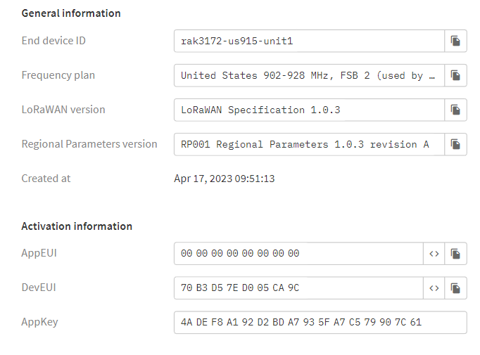
Still, here’s the bin file that worked on my test mentioned above and also parameter you can use in your own LNS is on the image below. This one uses TTN. I hope this can help on your investigation.
Your bin file works! Already made memory dump. Now I am super curious how the same sketch compiled is different. Just for clarification:
-Board: 3172 Eval Board
-Debug: Level 0 (Release)
thank you for this. Finally, I was able to understand what was going wrong. (1) My first assumption about unstable power sources was right but only somewhat. The Code seems to correct its own flash when updating but this does not always work. It looks that an instable power source - e.g. from a weak USB/UART can impact this updating process then resulting in a partly corrupted flash. Having solid external power overcomes this. However, there is still the problem, of why it is possible to compile a firmware that does generate the TX_TIMEOUT error. You wrote me that the compile bin file was equal to the one you make locally but I doubt this. I was finally able to generate two different .bin files on two identical PCs using identical IDE and RAK packages (can share if you need it). I looked into the built process and realized that some of the object files differed ( namely stm32wlxx_it.c.o, uhal_flash.c.o and core.a) I changed the low level device driver and added some debug to see what goes wrong in detail and indeed the initialization of the LORA subsystem was different. Incorrect initialization of the LORA hardware results in missing IRQ on TX finally generating the error message TX_TIMEOUT. So far so bad. The final question is how it is possible that same code generates different object files and the answer is likely some caching in the temp directory. This remains a mystery but complete delete of the RAKRUI package plus reinstall ( not update!) solves this problem.
As net-net I would conclude it’s risky to just update the RAK RUI package in Arduino ide. Always delete and reinstall.