Hello,
Recently I am using RAK3172. Here I am using STM32 CUBE IDE and STM32 utility because I want to flash the program in RAK3172 using ST-LINK /V2 Clone.
Firstly ST-LINK connection with RAK3172
ST-link RAK3172
GND pin–>GND
SWDIO–>SWDIO
SWCLK–>SWCLK
NRST–>reset
BOOT0–> HIGH
And gave an external power of 3.3 Volts to RAK3172 .
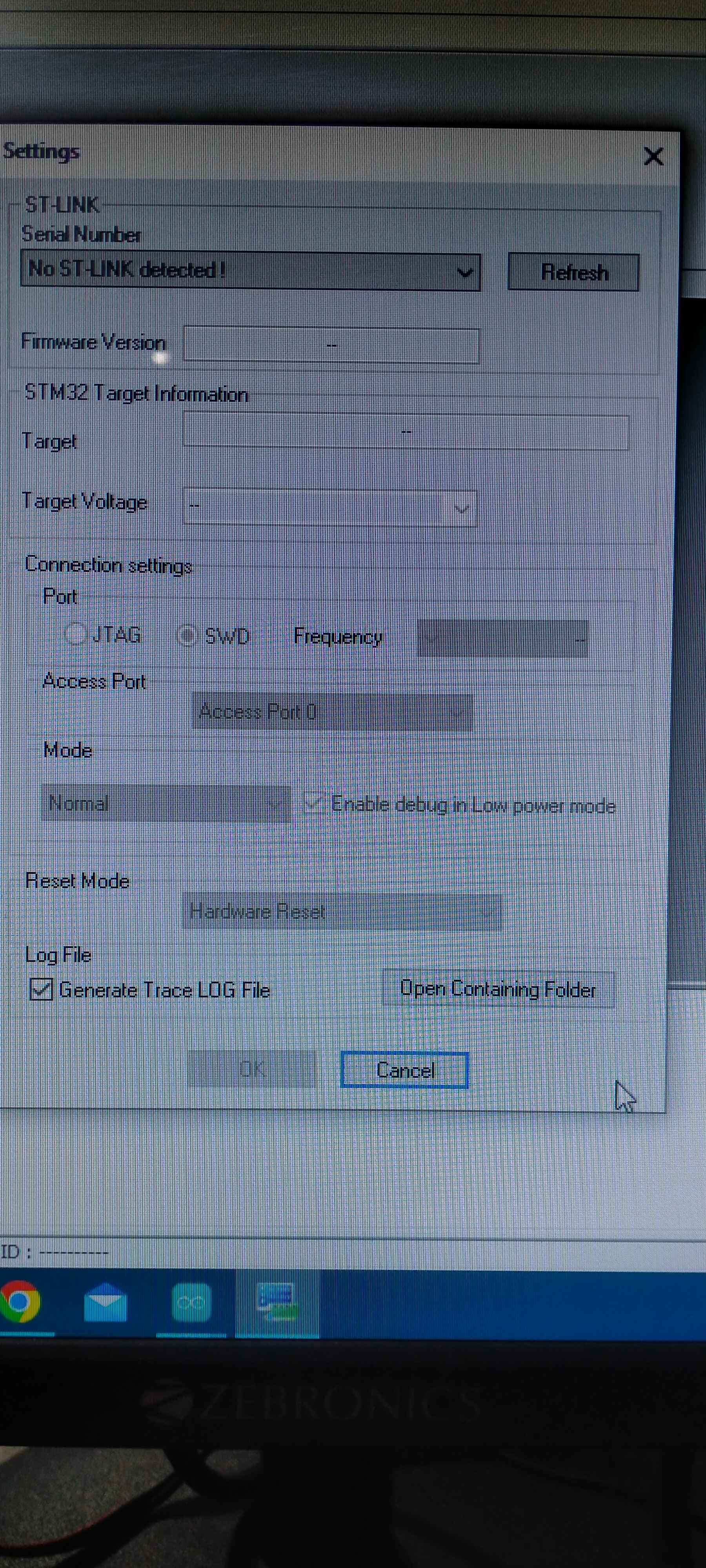
so when I opened the stm32 ST link utility. I got that the Error “No ST-LINK detected”.
Can you please help me to solve this problem ?
Welcome to the forum @Namma
Your connections are ok, but
Points towards a problem with your “cloned” ST-Link.
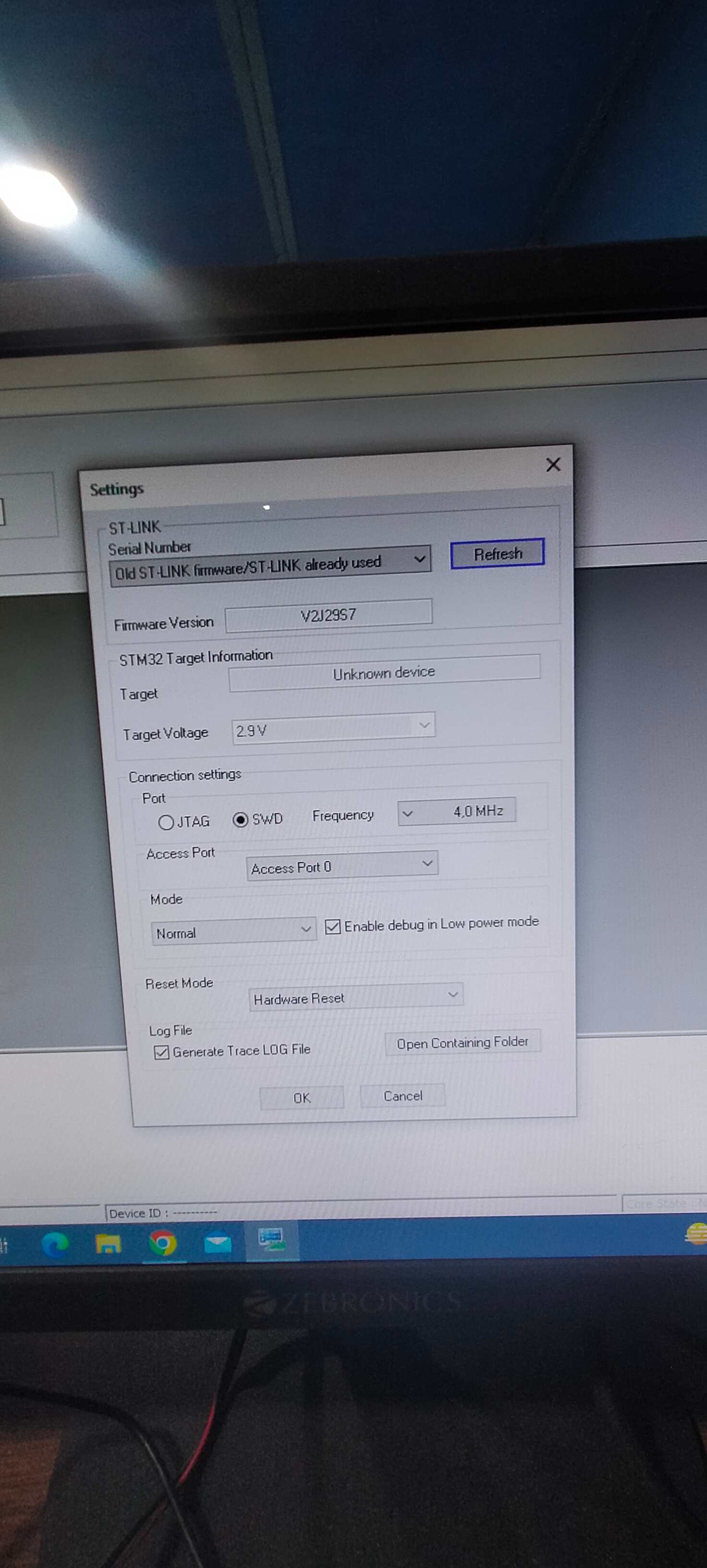
but When I didn’t connect the reset to NRST. I got the serial number but target was not available.
Can you flash without reset connected?
I don’t know .
may you please explain me about it?
Keep reset disconnected from the RAK3172 and ST-Link.
Connect the other lines, including BOOT0
power up the 3.3V
check if your ST-Link is available and flash the firmware
OK ,thank you let me check?
Hello Sir,
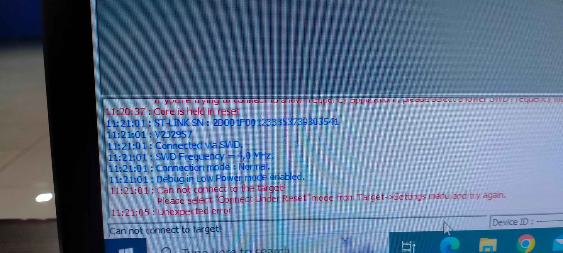
I saw one more result that all the connection was as usual as before I described. I connected a reset circuit with RAK3172 .so when I pressed the reset button I got the port and target device both .but when I released the reset then I didn’t get port and target device too. if I pressed the reset button continuously and try to flash the hex file I got the error “Core is held in reset”.
No idea what’s wrong. I have no ST-Link, so I cannot test.
Maybe someone else who owns a ST-Link can help.
Hi Nazneen
I had big issues with using SWD and RAK3172.
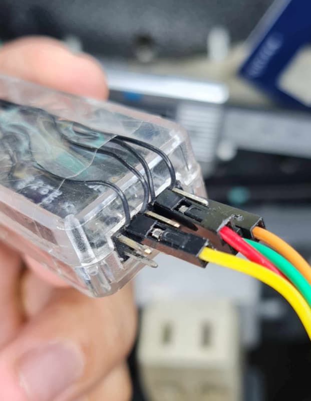
My setup looks very similiar to yours. Programmer, connector, wires and the module.
The length of the wires from the programmer to the module were in total less than 15 cm. About 7 cm from the programmer to the breadboard and about another 7 cmd from the breadboard to the module.
It did not work. Segger J-Link EDU and ST-Link V2 could not find the device. No matter what reset method was used.
I then reduced the length of the wires from the breadboard to the module to about 1 to 2 cm.
Now J-Link und ST-Link found the device. The device could be flashed as well.
I also tried a pull-up of 10 k on SWDIO and a pull-down of 10 k on SWCLK. It did not help. Only the short cable length made a difference.
I have the feeling that this is unusual. It should not be a matter of a very few centimeters to let the programmer connect to the microcontroller.
But for now it is that way. Maybe there is an expert on SWD here somewhere…
Hi @tb4450 ,
I am not an expert on SWD but I generally avoid breadboards and jumper wires.
I had experience/s before that these two prototyping methods causes me wasted hours of troubleshooting.
If there is a way that you can have direct contact via connector in the PCB, that is the best. If not, have the best quality jumper wires you have.
It is very likely on the setup since both external tools (Jlink and STlink) can’t communicate to the module.
Yes, breadboards can be very annoying. That’s certainly true.
1 Like
I still have a breadboard but rarely use it.
For jumper wires, we cannot escape it. But good quality ones are needed. There are badly crimped jumper wires.
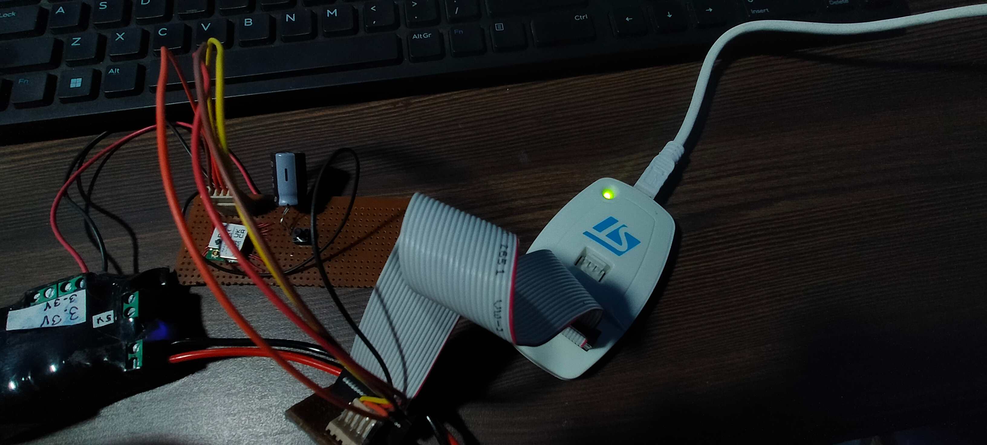
This is my RAKDAP1. It has jumper wires, yes. But I also have the 4 tiny wires directly soldered on the pins inside then I solder the other end the module’s board in case it cannot be detected. This way, I surely removed the factor of the faulty jumper wires. Worse experience I had is that if I continuity check the jumper wires they are connected but has bad coupling in the header pins. So I still prefer soldered wires ( I am not sure if that’s extreme. I have trauma on troubleshooting for hours just to find out it is only the jumpers ![]() ).
).