I have the RAK13102 (Notecard carrier) and the RAK11200-C Espressif WisCore and Notecard WBGLW (Cell+WiFi). I’d like to use the Notecard Outboard Firmware Update feature of Notecard to OTA update firmware on the ESP32.
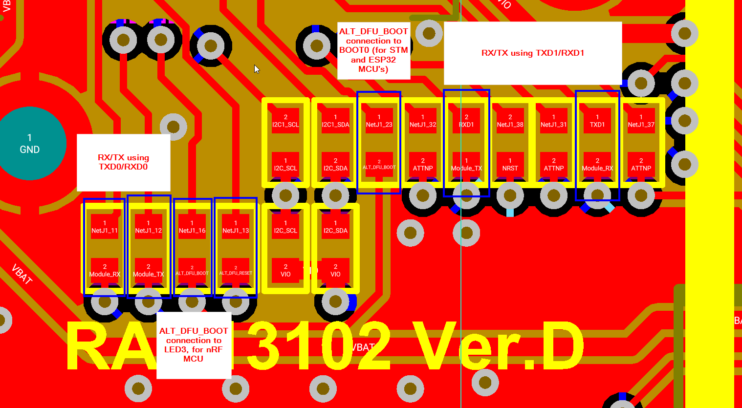
I’ve looked through the schematics, and it looks like the required signals (ALT_DFU_BOOT, ALT_DFU_RESET, ALT_DFU_TX/TXD0, ALT_DFU_RX/RXD0) are present (pins 11,12,13 and 23 on the WisConnector) to be able to control the BOOT0, RESET and UART0_TX/UART0_RX of the espressif module. However, in the schematic, it looks as though they are not connected on the RAK13102 unless a resistor/solder jumper is added.
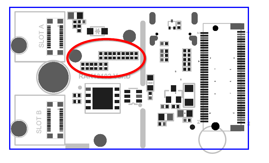
I’ve looked closely at the RAK13102 board, but I don’t see where I can make the modifications.
We added the option, but we never had time to test it, so we do not officially support or document it.
The resistors are on the top side of the PCB, all 0 Ohm
Some of them can be assigned to different nets.
Thank you @beegee for the information, now I know a little more.
Looking at the board, it seems most of them are depopulated, which of course makes sense. I’ll solder the bridges required and will let you know how it goes.
This will be crucial for our product for OTA firmware updates, as well as for automated hardware-in-loop testing.
Hi @elert-dev , did you finally check the possibility for OTA firmware updates on the ESP32 by using the Notecard? Any help will be appreciated. Best regards.