Hello! One of my homemade smart home devices is working.
as an infrared temperature sensor (RAK12003, open fire or body temperature) and an indicator of color temperature and illumination. Color temperature and illumination data are used to determine open combustion, time of day morning-afternoon-evening, light level, and other things.
The two sensors work together and perform multiple tasks.
IR Temperature Sensor (RAK12003) measures the temperature when an object (such as a person’s wrist) is brought near the device or when an RGB sensor interrupt is triggered. Also, the AMS TCS37725FN (RAK12021) sensor detects
color temperature and illumination in the room and transmits data via LoRaWAN. This is part of the smart home kit. It allows you to identify, for example, electric lighting that was left on out of forgetfulness.
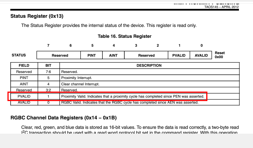
Everything works very well, but I recently realized that I can use the built-in proximity sensor of the AMS TCS37725FN to measure the temperature of an object the moment an object is brought to the IR sensor.
There appears to be some inaccuracy in the official code RAK12021-TCS37725.
Thus, proximity sensor data is not read in the getMeasurement() function
This is the function.
TCS3772_DataScaled TCS3772::getMeasurement(void)
{
  uint8_t i2cData[1];
  TCS3772_DataScaled scaledData;

// Probably due to the operating mode of the sensor, data is not read here

  readRegister(REG_PROX_DATAL | CMD_INCREMENT, i2cData, 1);
  scaledData.prox  = i2cData[0];

  readRegister(REG_PROX_DATAH | CMD_INCREMENT, i2cData, 1);
  scaledData.prox  += (i2cData[0]<<8);

//  readRegister(REG_PROX_DATAL | CMD_INCREMENT, i2cData, 2);
//  scaledData.prox   = (i2cData[1]<<8) + i2cData[0];

  return scaledData;
}
I know that the proximity sensor interrupt (unfortunately!) does not work in
Wisblock due to the electronic circuitry, but proximity sensor data must be output. Or are there any reasons why the AMS TCS37725FN proximity sensor data cannot be obtained?
A working proximity sensor would be very valuable for my programs, it could also work as an “electronic button”.
By the way, if the proximity sensor cannot be turned on, perhaps it makes sense to change the part of the library code that turns on the infrared LED? (to reduce power consumption)
// Should I change the datasheet here to 0x00?
i2cData = 0x5A;
  setRegister(REG_PULSE_COUNT | CMD_INCREMENT , i2cData , i2cData);// Set Proximity Time Register (0x02) to 0xFF.
Below is the code I use to work with beegee-tokyo/WisBlock-Sensor-For-LoRaWAN. I also added the necessary changes to initialization etc.
The code works stably and allows me to determine the type of lighting (color temperature) and the level of illumination in the room with sufficient accuracy.
Sometimes I use the AMS TCS37725FN sensor for photographic purposes as a “relatively accurate” colorimeter =)
// It use WB_IO2 to power up and is conflicting with INT1, so better use
// in SlotA/SlotC/SlotD.

// Slot A      WB_IO1
// Slot B      WB_IO2 ( not recommended, pin conflict with IO2)
// Slot C      WB_IO3
// Slot D      WB_IO5
// Slot E      WB_IO4
// Slot F      WB_IO6


#include "app.h"
#if RAK_RGB_ID > 0

#define INT_RGB WB_IO5
//#define INT_RGB WB_IO1

/* Sensor polling time for display */
#define INTERVAL_RGB 500
#include <Arduino.h>

#include "TCS3772.h"		// Click here to get the library: http://librarymanager/All#TCS37725
#include <math.h>

TCS3772 tcs3772;

volatile boolean g_threshold_exceeded = false;

void RGB_CallBack ()
{
  g_threshold_exceeded = true;
}

/* Clear channel Interrupt event */
void printEventSrc (void)
{
  uint8_t eventSrc = tcs3772.getInterruptSrc ();
  if( eventSrc & TCS3772_AINT)
  {
    /* Clear channel Interrupt event */
	MYLOG("RGB", "<<<<< event %d >>>>>>", eventSrc);
  }
  g_threshold_exceeded = false;
  tcs3772.clearAllInterrupt ();
}

/*!
* @brief Implements missing powf function
* @param x
* 	Base number
* @param y
* 	Exponent
* @return x raised to the power of y
*/
float powf (const float x, const float y)
{
  return (float) (pow ((double) x, (double) y));
}

/*!
* @brief Converts the raw R/G/B values to color temperature in degrees Kelvin
* @param r
* 	Red value
* @param g
* 	Green value
* @param b
* 	Blue value
* @return Color temperature in degrees Kelvin
*/
u_int16_t calculateColorTemperature (u_int16_t r2, u_int16_t g2, u_int16_t b2)
{
  float X, Y, Z;		// RGB to XYZ correlation
  float xc, yc;			// Chromaticity co-ordinates
  float n;			// McCamy's formula
  float cct;

  if (r2 == 0 && g2 == 0 && b2 == 0)
    {
      return 0;
    }
// https://ams.com/documents/20143/80162/TCS34xx_AN000517_1-00.pdf
/* Map RGB values to their XYZ counterparts. */
/* Based on 6500K fluorescent, 3000K fluorescent */
/* and 60W incandescent values for a wide range. */
/* Note: Y = Illuminance or lux */
  X = (-0.14282F * r2) + (1.54924F * g2) + (-0.95641F * b2);
  Y = (-0.32466F * r2) + (1.57837F * g2) + (-0.73191F * b2); // Illuminance
  Z = (-0.68202F * r2) + (0.77073F * g2) + (0.56332F * b2);

/* 2. Calculate the chromaticity co-ordinates */
  xc = (X) / (X + Y + Z);
  yc = (Y) / (X + Y + Z);

/* 3. Use McCamy's formula to determine the CCT */
/* CCT = 449n3 + 3525n2  + 6823.3n + 5520.33 */
/* where n = (xc − 0.3320F) / (0.1858F − yc) */
  n = (xc - 0.3320F) / (0.1858F - yc);

/* Calculate the final CCT */
  cct =
    (449.0F * powf (n, 3)) + (3525.0F * powf (n, 2)) + (6823.3F * n) +
    5520.33F;

/* Return the results in degrees Kelvin */
  return (u_int16_t) cct;
}


/*!
* @brief Converts the raw R/G/B values to lux
* @param r
* 	Red value
* @param g
* 	Green value
* @param b
* 	Blue value
* @return Lux value
*/
u_int16_t calculateLux (u_int16_t r2, u_int16_t g2, u_int16_t b2,  u_int16_t c)
{
  float lx;
 /*
     ms    luxmax       der
     50 134333.33   += 12.4
    100  67166.67   += 6.2
    150  44777.78   += 4.13
    200  33583.33   += 3.1
    250  26866.67   += 2.48
    300  22388.89   += 2.07
    350  19190.48   += 1.77
    400  16791.67   += 1.55
    450  14925.93   += 1.38
    500  13433.33   += 1.24
    550  12212.12   += 1.13
    600  11194.44   += 1.03
 */
        /* Device specific values (DN40 Table 1 in Appendix I) */
        const float GA = 1.f;        // Glass Attenuation Factor
        static const float DF = 310.f;             // Device Factor
        static const float R_Coef = 0.136f;        //
        static const float G_Coef = 1.f;           // used in lux computation
        static const float B_Coef = -0.444f;       //

	/* Analog/Digital saturation (DN40 3.5) */
        int atime = 2.4 * 64;
        float saturation = (256 - atime > 63) ? 65535 : 1024 * (256 - atime);
        /* Check for saturation and mark the sample as invalid if true */
        if (c >= saturation)  return 0;

// Lux calculations are also simple but have fractional coefficients.
// One trick is to multiply the coefficients by 1000 making them integer
// values and using ATIME in microseconds (also an integer) to cancel out
// this multiplication.
// Gi” = 136 * R’+ 1000 * G’ +(-444) * B’
// Note that CPL is calculated only when the ATIME or AGAIN has changed.
// This is why it is shown as a separate calculation.
    /* Lux Calculation (DN40 3.2) */
    // The color Lux equation is a function of the R’, G’ and B’ channels and
    // associated color coefficients creating a G” as follows:
    // G” = R_Coef * R’ + G_Coef * G’ + B_Coef * B’
        float g1 = R_Coef * r2 + G_Coef * g2 + B_Coef * b2;

	/* Set the internal integration time as 2.4*64 ms. */
	// ATIME = 256 − Integration Time / 2.4 ms
	// ATIME = 192 = 256 - 153.6/2.4
	// Inversely, the time can be calculated from the register value as
	// follows: Integration Time = 2.4 ms × (256 − ATIME)

	/* CPL = (ATIME_ms * AGAINx) / (GA * DF) */
        float cpl = (2.4 * 64) / (GA * DF);
	/* Lux = G” / CPL */
        lx = g1 / cpl;
	// lx = (-0.32466F * r2) + (1.57837F * g2) + (-0.73191F * b2);
  return (u_int16_t) lx;
}

// Device  GA*  DF   R_Coef G_Coef  B_Coef  CT_Coef CT_Offset
// TCS3472 1.0  310  0.136  1.000  -0.444   3810    1391
// TCS3772 1.0  310  0.136  1.000  -0.444   3810    1391

u_int16_t calcTemperatureDN40 (u_int16_t r2, u_int16_t b2)
{
  float cct;
  /* Device specific values (DN40 Table 1 in Appendix I) */
  static const float CT_Coef = 3810.f;   // Color Temperature Coefficient
  static const float CT_Offset = 1391.f; // Color Temperatuer Offset
  /* CT Calculations (DN40 3.4) */
  // CT (degrees Kelvin) = CT_Coef*(B’/R’) + CT_Offset
  cct = (CT_Coef * b2) / r2 + CT_Offset;
  return (u_int16_t) cct;
}

bool init_rak12021 ()
{
    Wire.begin ();		//I2C init

  if (tcs3772.begin () == true)
    {
      MYLOG ("TCS34725", "Found sensor TCS34725");
 tcs3772.setClearLowThreshold (25);
 tcs3772.setClearHighThreshold (1000);
 tcs3772.enableClearINT ();
 tcs3772.clearAllInterrupt ();
 pinMode (INT_RGB, INPUT_PULLUP); // Connect with TCS37725 INT1.
 attachInterrupt (digitalPinToInterrupt (INT_RGB), RGB_CallBack, FALLING);
    }
  else
    {
	/* No TCS34725 found */
	return false;
    }
	return true;
}

void read_rak12021 ()
{
  TCS3772_DataScaled tcs3772_data = { 0 };
  tcs3772_data = tcs3772.getMeasurement ();
  uint16_t r, g, b, c, p;
  u_int16_t cct0, cct1, lux;
  float sum, ir, r2, g2, b2;

      r = tcs3772_data.red;
      g = tcs3772_data.green;
      b = tcs3772_data.blue;
      c = tcs3772_data.clear;
      p = tcs3772_data.prox;

    /* AMS RGB sensors have no IR channel, so the IR content must
    be calculated indirectly.  IR Rejection (DN40 3.1) */
      // IR = (R+G+B-C) / 2
      sum = r + g + b;
      // ir = (r + g + b > c) ? (r + g + b - c) / 2.f : 0.f;
      ir = (sum > c) ? ((sum - c) / 2.f) : 0.f;
      r2 = r - ir;
      g2 = g - ir;
      b2 = b - ir;

	 r = (float)r / c * 255.0;
	 g = (float)g / c * 255.0;
	 b = (float)b / c * 255.0;


      lux = calculateLux (r2, g2, b2, c);
      cct0 = calculateColorTemperature (r2, g2, b2);
      cct1 = calcTemperatureDN40 (r2, b2);
/*******************************/
// Here should be a code that allows you to cut off deliberately false color temperature results
/*******************************/

	MYLOG("RGB", "Sensor (~%d'K) %d'K Lux %d' ", cct0, cct1, lux);
	MYLOG("RGB", "r %d' g %d' b  %d' dc' %d p' %d", r, g, b, c, p);

	  if(g_threshold_exceeded == true)
	      {
	        g_threshold_exceeded = false;
	        printEventSrc();
	      }
	g_solution_data.addLuminosity(LPP_CHANNEL_LUMINOSITY, lux);
	g_solution_data.addColour(LPP_CHANNEL_COLOUR, r, g, b);
}

#endif