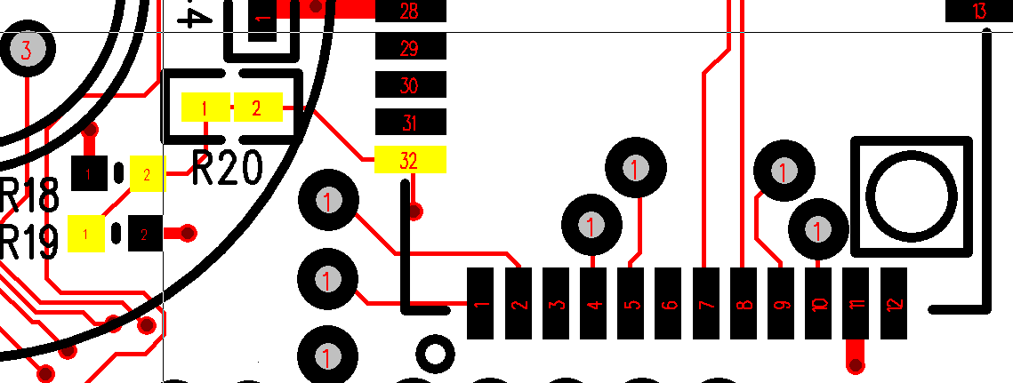
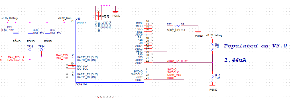
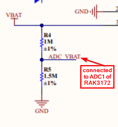
The 3.6V battery is connected to a 1M and 1M5 resistor to 0V
The connection between the 1M (R18) and 1M5 (R19) measures 1.98V and we have confirmed that 1.98V is on Pin32 on the RAK3172 Module. (R22 is just a 0ohm Link)
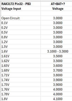
If you use the AT+BAT command, it will be clipped to 3.0V
There is custom algorithm on it (not direct ADC conversion) to compensate on the input impedance requirements on the analog pin of the STM32WL inside RAK3172.
With regards to 3.6V input but still shows 3.0V, were you able to check other voltage levels? Also, what type of battery are you using?
If you use direct voltage on PIN 32 to test, you will have different result.
The AT+BAT routine accounts the contribution of the voltage divider and its effect to the ADC input pin so I advice to use actual battery.
If you look on possibilities or workaround, these are some ideas I have (maybe @beegee has other ideas too):
Use lower resistor values and create a custom AT command that will measure the battery using ADC read api. If you need to maintain low power, might not be a good solution.
Remove the voltage divider and use separate circuit to measure the battery voltage. This can add cost but can be a reliable alternative. The external approach can range from actual ADC chip or even simple voltage monitor with trigger output.
Unfortunately problem this has occurred due to incorrect documentation from RAK . There is information regarding using the 1M & 1M5 resistor in various place and absolutely no mention in AT Command manual for the RAK3172 - AT+BAT=? regarding any problem
I tried different voltage values into Pin32 PB3 of the RAK3172 but do not understand how a 4.1V battery connected to the 1M & 1M5 resistor deviders can read the correct battery voltage
Your suggestions below
Can RAK (or anyone else) help in providing RUI3 4.1.1 for the RAK3172 which has a new AT command to read the ADC Voltage at Pin32 - PB3
We have 1000 PCBs ready to ship and therefore redesign is obviously out of the question at this stage
Custom AT commands are possible when using the RUI3 API.
But I am not sure if that would solve your problem with measuring voltages as low as you show in your table.
RAK3172 working voltage is 2V to 3.6V. Can you elaborate why you need to read such low voltages on a battery? If this battery is the direct supply to the RAK3172, it will have stopped working already.
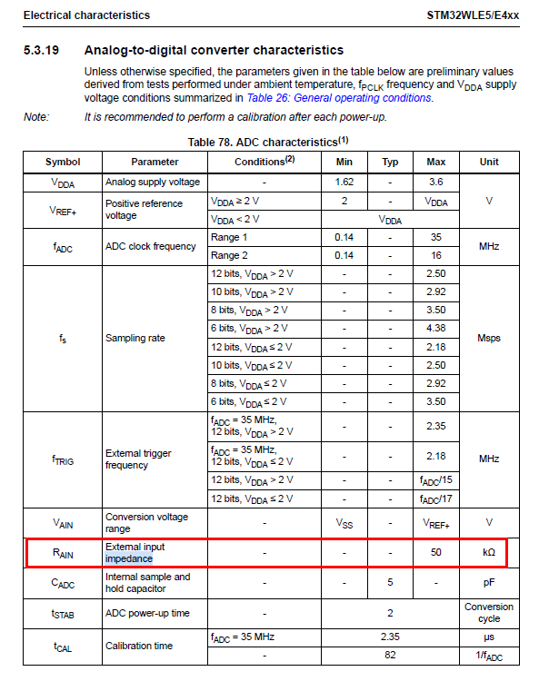
Using a custom AT command and reading the ADC input will require a translation table as well, as the ADC input has the hardware limitation of max 50kOhm:
We where under the illusion that we could read the 3.6V Battery voltage via PB3/ADC1 according to information on the forum and the RAK3172 AT Command Manual - AT+BAT=? - but this information seems incorrect
We have used the AT+BAT=? on the RAK3172-SIP without problem and we have manufactured 1000 boards using the 1M and 1M5 resistor divider - and therefore we must find a solution - because it does not work.
One method would be to “guess” the voltage based on the FCNT and SF number but I am not keen.
The chart in the previous messages is showing the voltage at the RAK3172 Pin32 - PB3/ADC1 - This is not the voltage that powers the RAK3172 but the voltage at the junction of the 1M and 1M5 resistor
So questions
What is the purpose of the AT+BAT=? when used on the RAK3172 ?
Is there any code or documentation that describes the AT+BAT=? command ?
Please explain your comment - “This means such a table has to be created and will not be accurate, same as AT+BAT, due to the variances in the resistor divider”
How does AT+BAT=? work correctly on the RAK3172-SIP ?
Can RAK Wireless create a special binary/hex to overcome this problem for the 1000off PCBs
We use a slave processor that could be used for translating the ADC1 voltage to generate the correct battery reading ?
(1) AT+BAT works only on WisBlock Base Boards or when you implement the same voltage divider circuit that is used on the Base Boards
(2) AT+BAT documentation, there is nothing beside of that.
(3) Our translation table covers only 3.0 to 4.2V battery voltage and was created by measuring from multiple devices multiple times. To get values below 3.0V we have to extend this and redo the measuring for lower voltages. However, as resistor values have a tolerance, STM32WLE5’s have a tolerance, this will never be very accurate.
(4) Same as (1), it “could” work if the same voltage divider is implemented, however, I never tested that.
(5) From your schematic I see that VBAT == VCC. Inside the RAK3172 VCC is VRef, so you have a problem here to read the battery voltage. VRef changes while VBat changes. There is no fix that I could think off.
(6) AT commands do not provide you with a command to read the ADC directly and send it to your host MCU, at this moment this is not a solution.
I did some investigation on this and in my opinion, if you need accurate reading AT+BAT might not be the best approach. The primary cause of this is the high value resistors used on the divider. This is done to save power consumption but it goes beyond the input impedance requirement of the analog pin. Few things we can do to improve this is use lower resistor values (max should be 50k) then implement direct ADC measurement and without the builtin adjustments of the AT+BAT command.
