Bought RAK3172 Breakout Board from Ali express so not sure it is in a good state in the first place.
It is not communicating with Arduino IDE, while downloading, it says not in boot mode.
I try putting it in boot mode by connecting boot pin to 3.3V and power cycling the module. Get the same response.
The module does not respond to AT+ver serial command as well, through Arduino serial window.
Furthermore does not communicate with DFU firmware tool as well. It says nothing found on serial port.
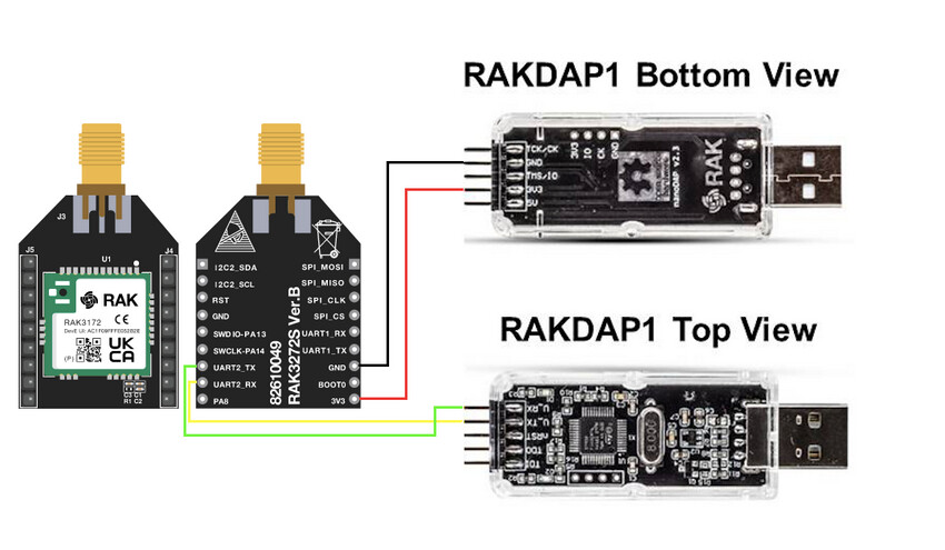
I am using following converter:
Is there any way I can confirm if RAK module is all good ? and not bricked. Thanks.
Make sure to connect to UART2
Make sure to cross RX/TX lines
Make sure that the adapter provides 3.3V
Make sure to setup your terminal to 115200 Baud 8 bits no parity 1 stop bit
Thanks @beegee for the response. Appreciate it.
I made sure all the points you shared remain valid as I connect to RAK3172.
Interestingly the module isn’t willing to communicate with any of the following platforms:
Arduino IDE
DFU Firmware Update Tool
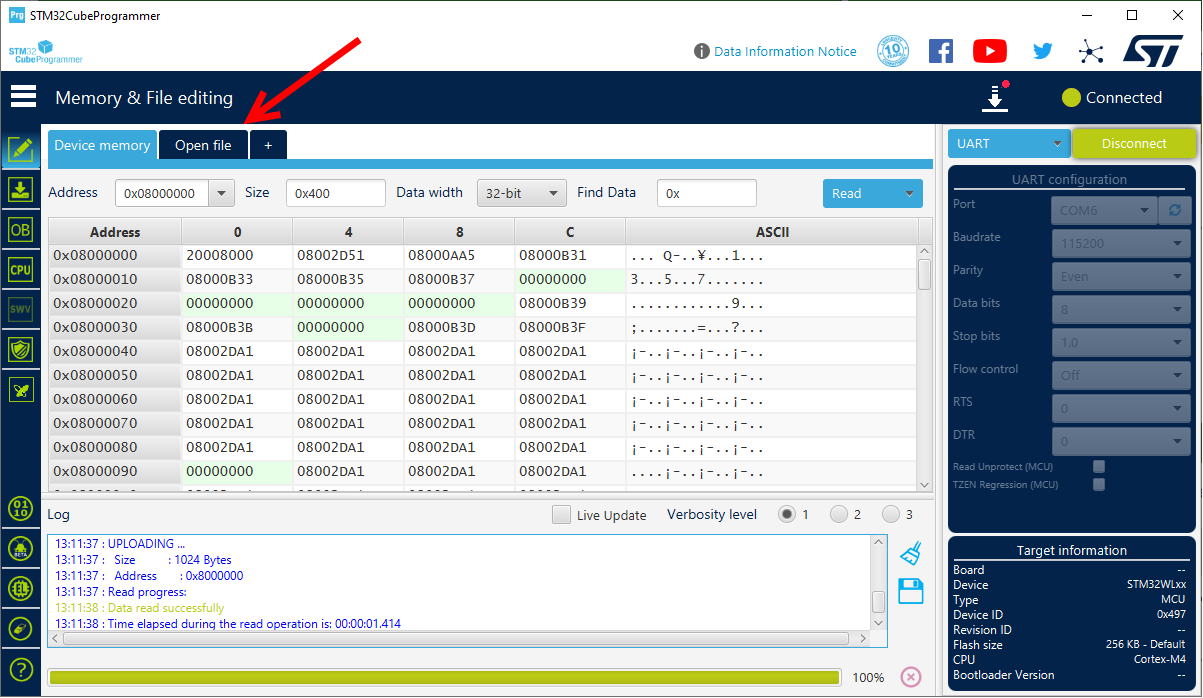
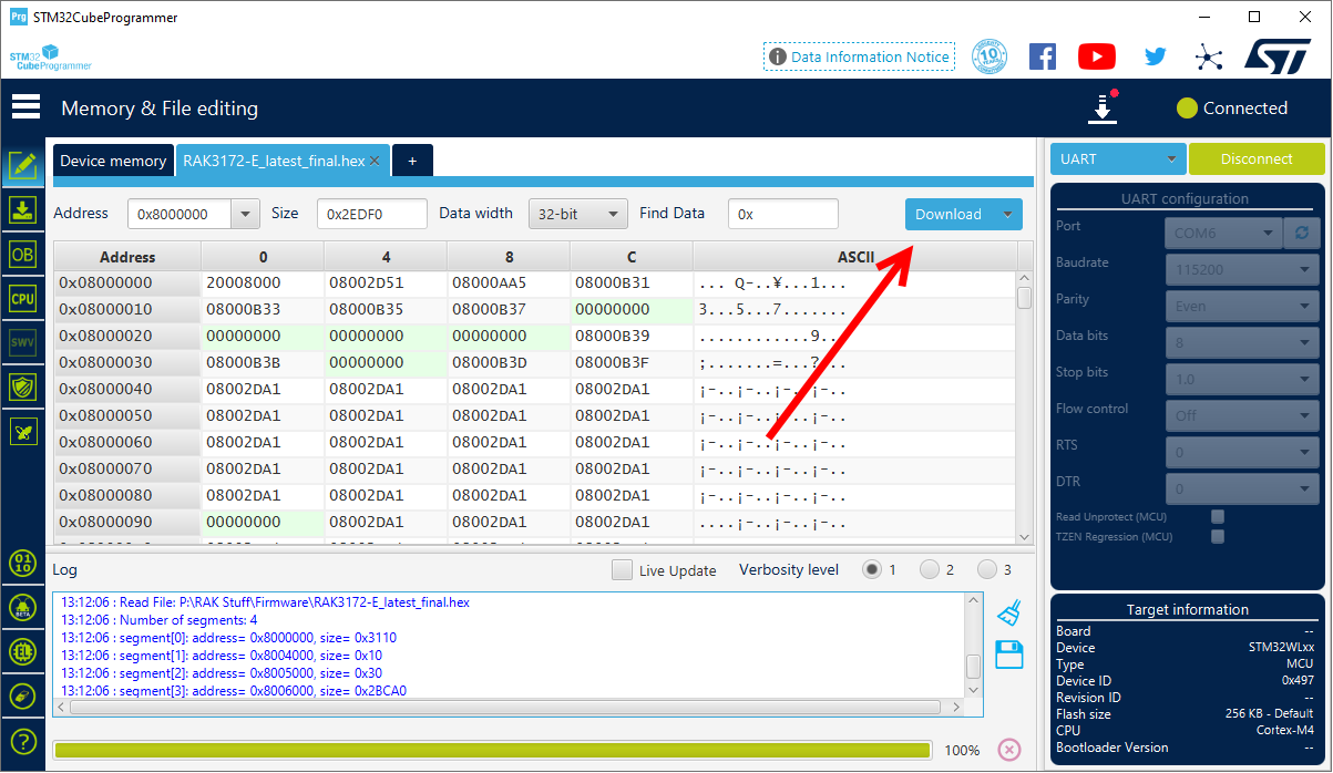
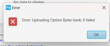
STM Cube Software (for downloading firmware)
I am fairly sure the FTDI works fine, since tested it with other boards. I just want to rule out that I got a bad module from Ali Express. Next time, I’ll try ordering from rak website. I thought to first check if I am missing something in wiring.
Don’t do that. That works only with the STM32CubeProgrammer.
Our DFU tool and Arduino IDE WILL NOT WORK if you connect BOOT0 to 3.3V, it has to stay open.
Thanks @beegee for highlighting this point, I tried with this combination as well but in vain unfortunately. I think the module itself might be bricked.
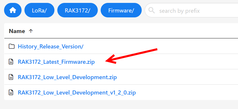
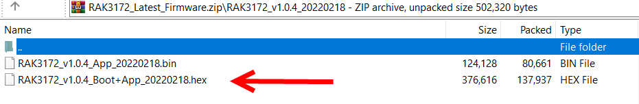
I’ve had a few 3172s come to me that behaved this way, and it turned out (for whatever reason) that the RAK firmware on them was either missing or somehow corrrupted such that loading applications onto them through the Arduino IDE was a no-go. The solution was a complete re-flash that includes everything, including the RAK bootloader.
Remove the jumper to BOOT0 and reset the chip - you should now be able to program the device from the Arduino IDE. Note that the message “device not in BOOT mode” is normal, but if you wait a few seconds, the upload will proceed anyway. I’m given to understand that you can explicitly put the device into boot mode by issuing an “AT+BOOT” command before attempting an upload, but I’ve never bothered.
I hope this works for you - I’ve had to do this with several 3172s acquired through AliExpress.
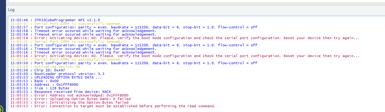
I’m almost suspicious of that particular FTDI adapter. I’ve never had a bad product from SparkFun, but the fact that your log shows a few unsuccessful attempts to get an acknowledgement from the 3172, but then manages to establish a connection and get a chip ID on the third try (only to have the next operation fail)…
The adapters I use employ exactly the same FTDI chip that appears on the SparkFun board - but one of the things that I find irksome about the design is that the 3.3V supply is coming from the FTDI’s internal LDO rather than an external regulator. According to the spec sheet, this is only designed to supply 50mA. I’ve never had a problem programming with a board of this design, but I notice that once the code starts running, the LEDs dim during a join or uplink.
Wondering if your mileage would vary with a different USB to serial adapter?
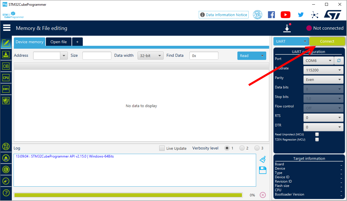
I am using the STM32CubeProgrammer a lot. Sharing some thoughts based on my experience.
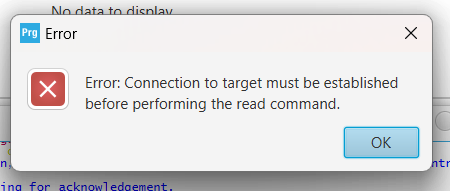
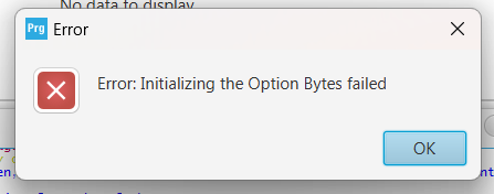
Poor connection on Supply and UART lines. Make sure they are connected firmly. It seems you are already established connection but suddenly stopped along the way with various errors showing up.
Not fully working USB-UART converter. My RAKDAP1 never ever worked on STM32CubeProgrammer. I have no idea why for others, it works fine. You can try a different one.
If supply of 3.3v is coming from the USB-UART converter, make sure it sustains the 3.3v. I’ve seen built-in 3.3v regulator on some USB-UART chip that are damaged. You can check the 3.3v with voltmeter.
Worst is that the chip is already damaged. It can still happen but I can’t recall I experienced one. If it can still be detected by STM32CubeProgrammer, then very likely it should still be ok. One thing I look on chips if damaged is its current consumption. Maybe you can have a look if it is not absurd.