A quick question regarding RST pin schematic recommended for RAK3172.
The Reset pin seems to be “Active Low”. As per above, RST pin would normally be High.
Would that impact sleep current ? Result in more sleep current ?
To introduce a manual reset, I need to place a switch parallel to the resistor ?
Thanks.
Thanks @carlrowan for the reply.
Apologies for the ignorance, as I am new to the group and not fully across RAK3172 documentation.
So the above circuit will keep the RAK3172 in reset state then ? Does that mean that the device will not work ? As it keeps resetting the device ?
I am confused a bit on this, can you please explain a bit more ? Thanks.
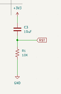
At power on, the capacitor C3 is discharged, the RST line is low. The capacitor will charge itself through the resistor R1 until the RST line is high enough to allow the RAK3172 to start up.
If you need a button for manual reset, it would be parallel to C3 from RST to GND.
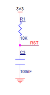
A capacitor along with push button should be enough I assume, from the snapshot above,
Was there a specific need to recommend using an external pull up resistor ?
It is a common practice to have external pullup. I can think of some reasons.
You can define and control the resistance value externally. Internal pullups usually are higher than 10k ohms (which is commonly used). Lower resistance is more reliable too.
Redundancy. In event that the internal fails, you have external one that can be secure the state.
Reliability. It is very likely that you have a stable pull-up tied to the correct voltage since the resistor is directly tied on VDD line.