I noticed a serious issue on consumption in transmit with EU868 (not tested other plans). I thought it was on my custom firmware and driver port for mbed-os so I tried with official port STM32WL RAK made for custom firmware but it’s the same thing. So I gave a 3rd try with your official AT Firmware and it’s the same issue.
Let me explain on EU868 transmit is limited to 14dB and all nodes only need approx 40mA max to do that. I understood that RAK3172 can only use RFO High Power path and not RFO_Low Power but since we transmit to 14dB we should not be impacted by this mode right?
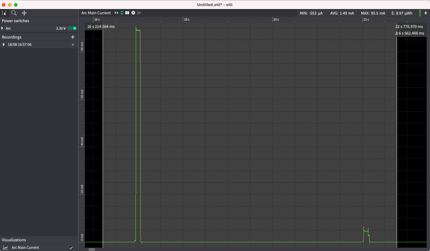
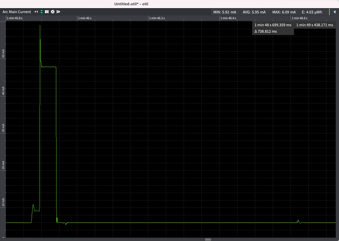
But it seems activating RF_HP for 14 dB power has a bad side effect because the module consumption is going to 90mA instead of 40mA, check the capture here.
Is it possible it has to do with Antenna tuning? I’ve observed a huge variation in TX power consumption even by just de-tuning the antenna by placing my finger on it. Do you have a VNA you could analyze the impedance of your antenna with?
@mintenj good point, but the antenna has been matched by antenna RF company, and I got same with All breakout boards I made with RAK3172 (with iPex and not)
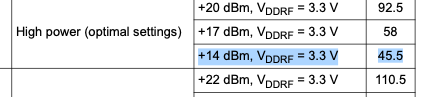
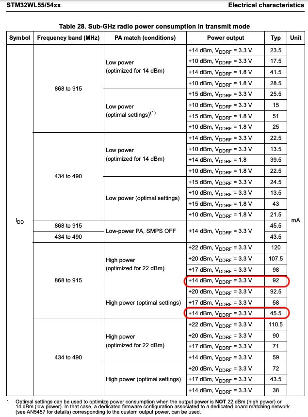
Have you correctly set the PA settings? On page 69/146 in the STM32WLE5CC datasheet, it appears the power consumption should be 45.5mA for the HP PA at 14dBm when optimized for 14dBm, but 92mA when optimized for 22dBm. It would only be 23.5mA if the RAK3172 could connect the LP PA rather than the HP PA. It does look like the PA settings do alter the output impedance, which could affect the needed antenna matching circuitry.
@mintenj sure I thought the issue was on my side and in the driver I changed for mbed until I tested the board with RAK Firmware (so no way of an hardware error or firmware, at least on my side)
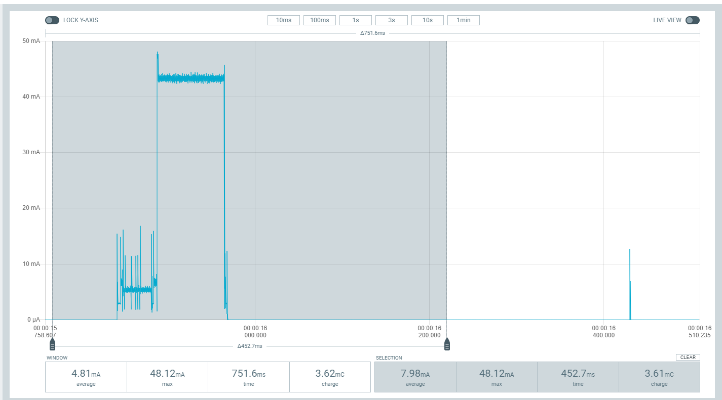
Here the settings I used with original RAK AT firmware when measuring
Set LoRaWAN Mode + OTAA + Class A + Frequency Plan EU868 (Band 4) + ADR
AT+NWM=1
AT+NJM=1
AT+CLASS=A
AT+BAND=4
AT+ADR=1
Join
AT+JOIN=1:0:10:8
OK
+EVT:JOINED
Now send message
AT+SEND=2:31323334
OK
+EVT:SEND CONFIRMED OK
But to be honest I think it’s by design (not using LP) because Seeed LoRa E5 has exactly the same consumption even with official LoRa-E5 dev board with official antenna.
It’s likely the internal matching circuitry only works with the 22dBm optimized PA settings. It would be complicated, and made even more complicated by their surprising lack of an internal schematic, but it may be possible to add additional external matching circuitry to enable the use of the 14dBm optimized PA settings. It would be great if RAK wireless could spec an external matching circuit for 14dBm optimized PA settings. The difference between 92mA and 45mA could be pretty huge for many applications, especially applications running off of batteries with high series resistance like coin cells.
Jacob,
mind crossing, you beat me, it was exactly my goal when I designed this board I made for CR2450 cell coin I was confident with 45mA peaks but 90mA, not so sure.
I have no good news to bring here but I hope the info I will share can bring some light. The 90mA is caused by having RF output available only on RFO_HP. Doing this simplifies the design of RAK3172 but with no option with RFO_LP out.
I agree with @mintenj that it can be probably done with optimum RF PA settings with the matching network but it is something we haven’t explored yet.
For everybody’s reference:
This is the optimized current consumption based on STM32WLE5CC datasheet
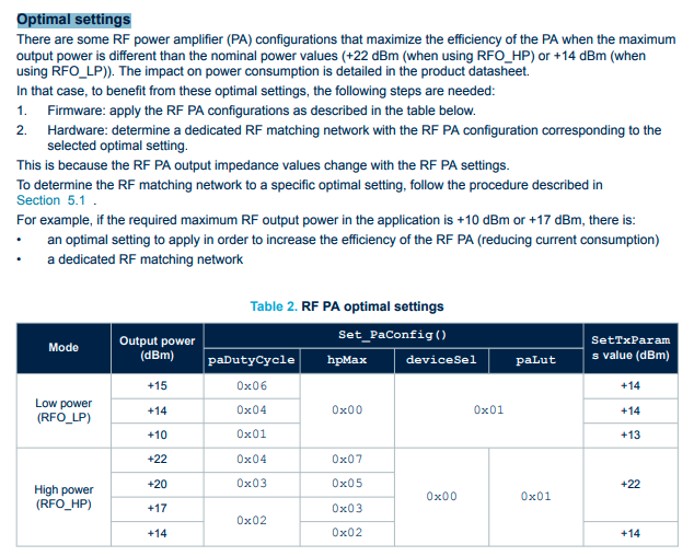
Here is the application note for tuning the RF which can make us lower the peak current of TX if optimized.
This info is useless without the RF matching network of RAK3172 so please have a look here:
And looking at my consumption it’s not the case and we are on 1st case. But even is for now we can’t change board matching network on module we can try changes on firmware side. Even if we surelly have some lost due to matching I’m pretty sure we can deal with is we are able to divider per 2 the consumption.
And in the document you attached here is what is said to do on firmware side
What is strange is that now got RSSI more logical compared to other devices near me, so I really suspect regarding RSSI I had before that we were transmitting over 14dBm and thus not respectincg the EU specs.
void STM32WL_LoRaRadio::SUBGRF_SetTxParams(uint8_t paSelect, int8_t power, radio_ramp_time_t rampTime)
{
    uint8_t buf[2];

    if (paSelect == RFO_LP) {
        if (power == 15) {
            set_pa_config(0x06, 0x00, 0x01, 0x01);
        } else {
            set_pa_config(0x04, 0x00, 0x01, 0x01);
        }
        if (power >= 14) {
            power = 14;
        } else if (power < -17) {
            power = -17;
        }
        write_to_register(REG_OCP, 0x18);   // current max is 80 mA for the whole device
    } else { // rfo_hp
        // Better Resistance of the radio Tx to Antenna Mismatch
        // RegTxClampConfig = @address 0x08D8
        write_to_register(REG_TX_CLAMP, read_register(REG_TX_CLAMP) | (0x0F << 1));

        // We are in rfo_hp ONLY but it's not optimal settings for other than +21dBm or +22dBm
        if (board_rf_switch_config == RBI_CONF_RFO_HP) {
            // so we need to handle settings sot rfo_lp equilavent that we don't have enabled
            // See Section 5.1.2 of Application Note
            // https://www.st.com/resource/en/application_note/an5457-rf-matching-network-design-guide-for-stm32wl-series-stmicroelectronics.pdf
            if (power > 20) {
                set_pa_config(0x04, 0x07, 0x00, 0x01);
            } else if (power > 17) {
                set_pa_config(0x03, 0x05, 0x00, 0x01);
            } else if (power > 14) {
                set_pa_config(0x02, 0x03, 0x00, 0x01);
            } else {
                set_pa_config(0x02, 0x02, 0x00, 0x01);
            }
        // In this case we have
        } else {
            set_pa_config(0x04, 0x07, 0x00, 0x01);
        }

        if (power > 22) {
            power = 22;
        } else if (power < -9) {
            power = -9;
        }
        write_to_register(REG_OCP, 0x38);   // current max 160mA for the whole device
    }
    buf[0] = power;
    buf[1] = (uint8_t)rampTime;
    write_opmode_command(RADIO_SET_TXPARAMS, buf, 2);
}
Do you have any update regarding this issue? I noticed that the latest AT firmware version is 1.0.2, but the documentation does not include any kind of version history. As a consequence, it is quite difficult to figure out if the latest AT firmware has been changed.
I am still going to use RAK3172 in my future products, but there is a very remarkable difference between 45 and 90 mA. Of course, I could make a custom firmware, which would also remove an external microcontroller from the board, but that solution would take some time. Meanwhile, a simple fix for the AT firmware would be very helpful.
Optimizing the RF PA configurations to lessen the power consumption also lessen the RF power out when our team measured it. It can compromise the range reachable by the end device. We are still looking for ways to optimize it which might involve some hardware modification on the RF passive frontend.
Btw, the initial version release is V1.0.2 so there is no change log yet. We will be releasing a new FW soon with the appropriate change log doc.
Based on the reports from RAK engineers it would seem this would need to be compared with some measurement of the actual RF output power.
Though it’s entirely possible you’re achieving the output power you need for your application.
Available supply voltage (under load) seems to be something that should be taken into account as well - with insufficient supply, the chip won’t achieve programmed output, and it may well be that it won’t achieve the output with some settings that it could with others.
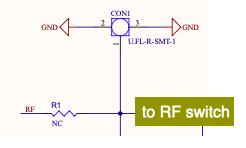
Thank you for providing the partial schematic. Just a quick question: Is there a difference in schematic between the IPEX and non-IPEX versions, or is the only difference that the IPEX connector is populated?
Reason I ask is I want to prototype with some various options with SMA and the IPEX. Could I purchase the IPEX version and connect only the antenna I intend to use? Whether it be to the IPEX or to the SMA, such as the RAK3272S breakout board design?
I guess what would answer the question is: Would the RAK3272S work just as well if it was populated with the IPEX version?
I’m thinking perhaps the track leading to the SMA connector would need to be disconnected if using the IPEX connector, and the IPEX connector would degrade the performance with an antenna connected to the SMA connector.
IPEX and non-IPEX RAK3172 have difference in schematic. A resistor that connects the RF pin (where the SMA of RAK3272S is connected) to the RF switch. Sadly, you cannot just use the IPEX variant to the RAK3272S breakout board (if that’s what you plan) without putting the tiny 0 ohm resistor.