=========== Question Parameters =============Connect analog input to the WisBlock system with the RAK5811 Module ). In many ways, it is a continuation of this closed discussion: RAK5811 0-5V module .
Using Arduino BSP.
Do not know how to get my RAK19001/RAK11310 to respond to AT+VER=? Have not used it with AT commands.
Running a Windows 11 PC, fully updated. Lots of success with RAKwireless products so far.
Not a problem with the product per se but with its documentation.
=============================
(1) When I look at the documentation at rakwireless-docs/docs/Product-Categories/WisBlock/RAK5811 at master · RAKWireless/rakwireless-docs · GitHub , I see no figures at all, not even placeholders. Have cleared browsing data on both Chrome and Edge browsers. Hard to understand the unlabeled device as a result. Feedback from GitHub maintainers is that they can see all figures. Can someone give me a clue?
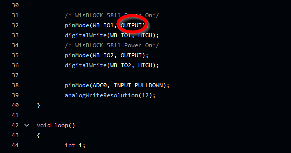
(2) Looking at the example ( WisBlock/examples/RAK11300/IO/RAK5811_0-5V/RAK5811_0-5V.ino at master · RAKWireless/WisBlock · GitHub ), Line 32 declares a pin to be an output pin but Line Line 33 writes to that pin. This is something I do not understand. Could someone please explain?
Many thanks for the community’s feedback.
beegee
November 9, 2024, 2:19am
2
Documentation is in {Documentation Center](RAK5811 WisBlock 0-5V Interface Module | Documentation Center ), not in Github.
Where do you see the GPIO declared as an input pin?
Many thanks for this.
Came upon the GitHub documentation while following links to examples. Will fix my own table of sources in the documentation I am writing.
That pin is set as an output pin but the next line writes to that pin. That is what is confusing me.
==============
Following the example at WisBlock/examples/RAK11300/IO/RAK5811_0-5V/RAK5811_0-5V.ino at master · RAKWireless/WisBlock · GitHub , after grounding A0 and A1, the following output appears on the Serial Monitor:
15:57:41.247 → -------voltage_sensor------ = 0.059096
Had expected to get 0.0 for voltage_sensor. There was no LoRa or WiFi running on the board at the time, unless something is running that I did not consciously turn on.
What am I missing? Trying to learn and document.
