Sleep Mode Current RAK3172

How are you building your application for the RAK3172? Looks like you’re using STM32Cube with LL function generation for PWR?

LL_PWR_EnablePUPDCfg();
LL_PWR_DisableGPIOPullUp(LL_PWR_GPIO_A,LL_PWR_GPIO_BIT_4);
LL_PWR_DisableGPIOPullDown(LL_PWR_GPIO_A, LL_PWR_GPIO_BIT_4);
LL_PWR_DisablePUPDCfg();

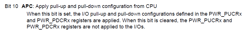
I think the LL_PWR_DisablePUPDCfg() turns off - undoes - the settings you did above. It turns off the APC bit in PWR_CR3. For the per-bit settings to work, at least remove that.

What power-down mode are you putting the MCU in? I think the PUPDCfg hardware applies to the MCU in the Standy and Shutdown states; if I recall correctly the MCU is in STOP2 state when running the LoRaWAN stack (at least with the ST LoRaWAN port). So I suspect these bits don’t apply here. It’s the regular pull-up/down configuration for the GPIO bits you need to address.

If you’re using the LL code generation, I think that’s LL_GPIO_SetPinPull() you want to set. In fact, I think you want to initialize the GPIO pull mode regardless of what low power mode you use.

Hope that helps -
Dana

I’m using RUI3 API on Arduino. I didn’t find the function to disable Pull-Up in RUI3, I tried to find something in the STM32WLE files, because I didn’t have an option. I have no knowledge about this API. I still haven’t found a solution.

I’ll check out your tips and try something new.

Sounds like the RUI3 BSP isn’t turning-off the pull-up when you choose pinMode(…, INPUT) vs INPUT_PULLUP. Perhaps @beegee can check on this?

Cheers,
Dana

Have you tried manually calling LL_GPIO_SetPinPull() after setting-up the pin?

I don’t have the source codes for RUI3 at hand, so I made a quick check.

pinMode(WB_IO1, INPUT); ==> ~0.25V on the pin
pinMode(WB_IO1, INPUT_PULLUP); ==> ~3.29V on the pin

So RUI3 does disable the pullups as expected.

Run the same quick test on PA4, PA5 and PA6 which are setup by RUI3 as SPI_NSS, SPI_CLK and SPI_MISO.
They show the same values. ~.25V when setup as INPUT , ~3.29V when setup as INPUT_PULLUP.

#include <Arduino.h>

void setup()
{
	Serial.begin(115200);
	pinMode(WB_IO2, OUTPUT);
	digitalWrite(WB_IO2,HIGH);
}

void loop()
{
	pinMode(WB_SPI_CS, INPUT);
	pinMode(WB_SPI_CLK, INPUT);
	pinMode(WB_SPI_MISO, INPUT);
	Serial.println("PA4 INPUT");
	api.system.sleep.all(15000);
	pinMode(WB_SPI_CS, INPUT_PULLUP);
	pinMode(WB_SPI_CLK, INPUT_PULLUP);
	pinMode(WB_SPI_MISO, INPUT_PULLUP);
	Serial.println("PA4 INPUT_PULLUP");
	api.system.sleep.all(15000);
}
1 Like

Excellent test, Bernd - could you try adding the interrupt handler?

attachInterrupt(D1_PIN, D1_HANDLER, FALLING);

Possibly the enables the pull-up as a side-effect?

Thanks -
Dana

@danak6jq
Good idea and you unfortunately you are correct with the side-effect.
If I add the attachInterrupt() the voltage levels are up to 3.3V and setting pin mode “Input” without pullup doesn’t work.

Now I am not a STM32 expert and I don’t know if the pullup is automatically enabled if you setup a GPIO as interrupt source.

I tried both attachInterrupt(WB_SPI_CS, int_handler, FALLING); and attachInterrupt(WB_SPI_CS, int_handler, RISING); and the result is the same.

1 Like

Thank you @beegee for running the experiment - very useful.

On a couple of RAK3172s here running firmware generated from a fairly enhanced branch of danak6jq/RAK3172: Port of STM32WLxx example for RAK3172 (github.com) - bare metal on the STM32WLE5 using STM32Cube - I’ve configured pins as external interrupts (EXTI) and they do not have the internal pull-ups configured. Here’s the Cube-generated code:

  /*Configure GPIO pins : PAPin PAPin */
  GPIO_InitStruct.Pin = INPUT_IO6_Pin|INPUT_IO5_Pin;
  GPIO_InitStruct.Mode = GPIO_MODE_IT_RISING_FALLING;
  GPIO_InitStruct.Pull = GPIO_NOPULL;
  HAL_GPIO_Init(GPIOA, &GPIO_InitStruct);

These have a total of ~500k as a pull-up externally (as part of a level-shifter) and show ~6.3uA when pulling one down. So I’ll try a quick experiment and set the Pull mode to GPIO_PULLUP, build, flash, and…

Indeed, with the internal pull-up enabled on the GPIO, I see ~83uA when pulling one down. So the RUI3 attachInterrupt() appears to be explicitly turning-on the internal pull-up as a side-effect.

Thanks for doing the experiments there!

1 Like

Gents

We are just about the start a simple design based on the RAK3172 monitoring two reed relays

Is there any conclusion to the above high current problems when using standard RUI3 ?

Any workaround ?

Kind Regards
Paul Humphreys

Up. Any update about that ?

Any update on this issue??

Thanks in advance.

Any update about this issue ?

Hello everyone!

From the datasheet:

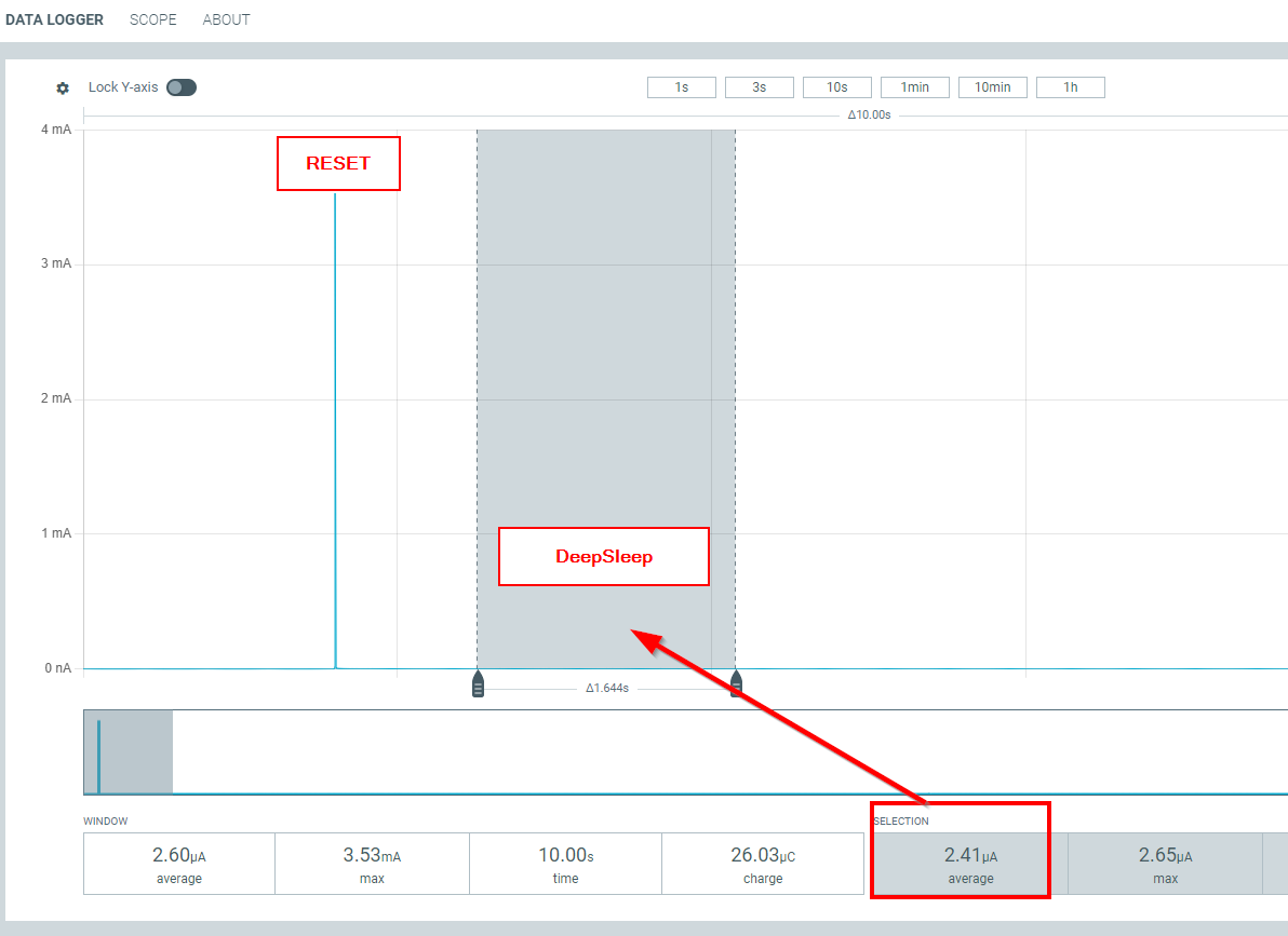
How can I achieve a current consumption of 1.67 µA? I measured the current on the module alone—with no pins connected—and I’m getting 20 µA (only the power pins are connected). Here is my code using the Arduino RUI Library:

void setup() {
}

void loop() {
api.system.sleep.all();
}

Welcome to the forum @lucas

Is this a plain RAK3172 module, a RAK3272 Breakout Board or a WisBlock RAK3372 Core module?

Hello!

Just a plain RAK3172 module with a RAK antenna IPC (PN: P-0205-02).

If you are using a custom FW, make sure you enable low power mode and stop RX mode.
In setup() add

// Enable low power mode
api.system.lpm.set(1);

If the device is set to LoRa P2P add

// Disable RX`
api.lora.precv(0);`

If the device is set to LoRaWAN add

api.lorawan.join(0,0);

You need as well to set the sleep level with an AT command

AT+LPMLVL=2

This has to be done only once, the sleep mode will be saved in the internal flash.

For reference, please check our RUI3-Best-Practice collection of sample application.
For low power mode we have the RUI3-LowPower-Example

Hello Bernd,
I tested and same power consumption.
What I observed it is that the serial RX are still running and waiting for a char.
Is it expected? Its possible do disable it?
For info: I`m using RUI_4.1.1_RAK3172-E_final.hex bootloader.
For which condition I can assume 2uA of power consumption?

Did you disconnect the RX/TX lines from the RAK3172?
How do you measure the consumption?

Minimum setup with RAK3172 Breakout Board
Measured with Nordic Power Profiler Kit II
Firmware RUI3-LowPower-Example
Setup to LoRa P2P, RX disabled.

PPK2 output:

Hardware setup:

AT+LPMLVL=2 reduced my consumption in deep sleep from 7uA to 3.5uA!!! There is a way to do this by api, without using AT+ command?

1 Like

There is none @mariojose . LPMLVL has been one of the recently added configurations on RUI3 so it is only available via AT command.