Sleep Mode Current RAK3172

Hello, I’m using RAK3172 (very good) with firmware 4.0.1. The application is counting the water meter reed switch pulses (using an external 1MΩ pullup) with an external interrupt (attachInterrupt).

The code goes into sleep mode, consumes ~5uA and wakes up regularly to send the counters. It also asynchronously wakes up to count pulses (interrupt pins generated by reed switch, connected to ground).

However, when the reed switch remains closed (PA4 pin shorted to ground) and enters sleep mode, power consumption increases, maintains about 88uA in deep sleep. After the reed switch opens (the pullup works), the current goes back to 5uA. In the same application using STM8L152 and setting GPI_Mode as GPIO_Mode_In_FL_IT (without internal pullup) the consumption was increased by + ~5uA and not by + ~80uA.

In this application I use 3 counters, so when the 3 switches are closed the consumption in sleep mode increases a lot (+ ~240uA in Sleep).

Do you have any suggestion? Thanks.

Screenshot_8

Hi @tiago.dsnts ,

Can you share us the complete code so we can see how sleep routine was implemented as well what the interrupt handler D1_HANDLER executes ones falling edge is detected? We can try to implement it and see what possibly causes it.

This code behaves exactly like my application (same functions, not changing a comma). I just removed the uplink payload because it’s irrelevant to the analysis.

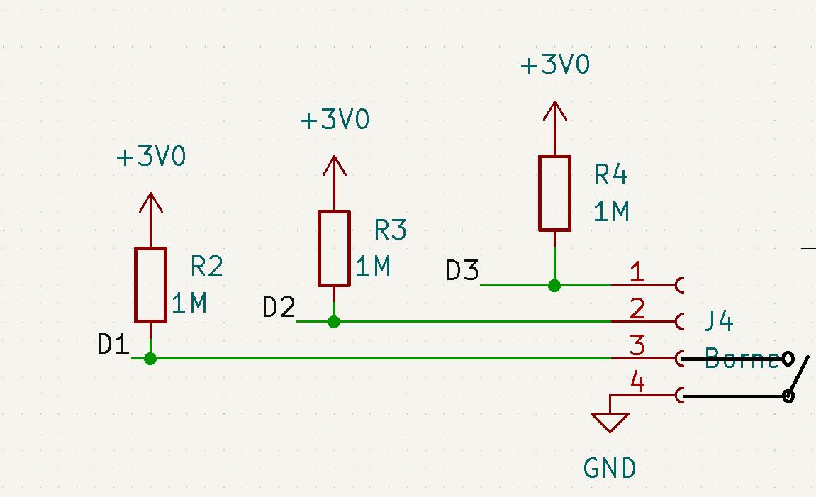
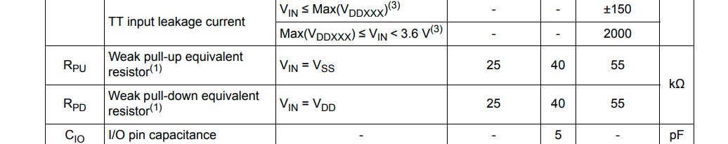
With all inputs open, sleep consumption is ~5uA. By placing the D1 input to GND, the consumption jumps to exactly ~88uA.

I didn’t use api.system.sleep.setup(RUI_WAKEUP_FALLING_EDGE, D1_PIN); because I could only wake up the microcontroller for a single input (I couldn’t count pulses on several inputs simultaneously, during sleep mode).

Code:

#define OTAA_PERIOD   (60000)
#define OTAA_BAND     (RAK_REGION_AU915)
#define OTAA_DEVEUI   {0x01, 0x02, 0x03, 0x04, 0x05, 0x06, 0x07, 0x88}
#define OTAA_APPEUI   {0x6a, 0x22, 0x2b, 0x60, 0x3f, 0x2e, 0xd0, 0xba}
#define OTAA_APPKEY   {0x6a, 0x22, 0x2b, 0x60, 0x3f, 0x2e, 0xd0, 0xba, 0x43, 0x3e, 0xfb, 0x10, 0x05, 0xb4, 0x4b, 0x1c}
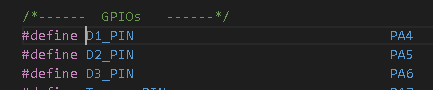
#define D1_PIN                                PA4
#define D2_PIN                                PA5
#define D3_PIN                                PA6
#define Tamper_PIN                         PA7
#define Bateria_PIN                          PB3

/** Packet buffer for sending */
uint8_t collected_data[64] = { 0 };

volatile uint32_t pulsosD1;
volatile uint32_t pulsosD2;
volatile uint32_t pulsosD3;
volatile unsigned long last_timeD1;
volatile unsigned long last_timeD2;
volatile unsigned long last_timeD3;
long deb_timeD1 = 200;                        // debounce time(ms) canal 1
long deb_timeD2 = 200;                        // debounce time(ms) canal 2
long deb_timeD3 = 200;                        // debounce time(ms) canal 3

static bool set_timer_sleep = true;

struct pulsosVar{
  uint8_t D1[8];
  uint8_t D2[8];
  uint8_t D3[8];
  bool tamper;
};

void recvCallback(SERVICE_LORA_RECEIVE_T * data)
{
    if (data->BufferSize > 0) {
        Serial.println("Something received!");
        for (int i = 0; i < data->BufferSize; i++) {
            Serial.printf("%x", data->Buffer[i]);
        }
        Serial.print("\r\n");
    }
}

void joinCallback(int32_t status)
{
    Serial.printf("Join status: %d\r\n", status);
}

void sendCallback(int32_t status)
{
    if (status == 0) {
        Serial.println("Successfully sent");
    } else {
        Serial.println("Sending failed");
    }
}

void uplink_routine()
{
    /** Payload of Uplink */
    uint8_t data_len = 0;
    collected_data[data_len++] = (uint8_t) 't';
    collected_data[data_len++] = (uint8_t) 'e';
    collected_data[data_len++] = (uint8_t) 's';
    collected_data[data_len++] = (uint8_t) 't';

    Serial.println("Data Packet:");

    for (int i = 0; i < data_len; i++) {
        Serial.printf("0x%02X ", collected_data[i]);
    }

    Serial.println("");

    /** Send the data package */
    if (api.lorawan.send(data_len, (uint8_t *) & collected_data, 2, true, 1)) {
        Serial.println("Sending is requested");
    } else {
        Serial.println("Sending failed");
    }
}

void D1_HANDLER()
{
    if(millis() - last_timeD1 > deb_timeD1)     // Debounce Time
    {
      pulsosD1++;                              
      Serial.printf(" D1++ %i\r\n", pulsosD1);
      last_timeD1 = millis();
    }
}

void D2_HANDLER()
{
    if(millis() - last_timeD2 > deb_timeD2)    
    {
      pulsosD2++;                              
      Serial.printf(" D2++ %i\r\n", pulsosD2);
      last_timeD2 = millis();
    }
}

void D3_HANDLER()
{
    if(millis() - last_timeD3 > deb_timeD3)    
    {
      pulsosD3++;                              
      Serial.printf(" D3++ %i\r\n", pulsosD3);
      last_timeD3 = millis();
    }
}

void setup()
{
    Serial.begin(115200, RAK_AT_MODE); 

    Serial.println("RAKwireless LoRaWan OTAA Example");

    Serial.println("------------------------------------------------------"); 

    if(api.lorawan.nwm.get() != 1)
    {
        Serial.printf("Set Node device work mode %s\r\n",
            api.lorawan.nwm.set(1) ? "Success" : "Fail");
        api.system.reboot();
    }

    // OTAA Device EUI MSB first
    uint8_t node_device_eui[8] = OTAA_DEVEUI;
    // OTAA Application EUI MSB first
    uint8_t node_app_eui[8] = OTAA_APPEUI;
    // OTAA Application Key MSB first
    uint8_t node_app_key[16] = OTAA_APPKEY;

    if (!api.lorawan.appeui.set(node_app_eui, 8)) {
        Serial.printf("LoRaWan OTAA - set application EUI is incorrect! \r\n");

        return;
    }

    if (!api.lorawan.appkey.set(node_app_key, 16)) {
        Serial.printf("LoRaWan OTAA - set application key is incorrect! \r\n");
        return;
    }

    if (!api.lorawan.deui.set(node_device_eui, 8)) {
        Serial.printf("LoRaWan OTAA - set device EUI is incorrect! \r\n");
        return;
    }

    if (!api.lorawan.band.set(OTAA_BAND)) {
        Serial.printf("LoRaWan OTAA - set band is incorrect! \r\n");

        return;
    }

    if (!api.lorawan.deviceClass.set(RAK_LORA_CLASS_A)) {
        Serial.printf("LoRaWan OTAA - set device class is incorrect! \r\n");

        return;
    }

    if (!api.lorawan.njm.set(RAK_LORA_OTAA))    // Set the network join mode to OTAA
    {
        Serial.printf("LoRaWan OTAA - set network join mode is incorrect! \r\n");

        return;
    }

    if (!api.lorawan.join())    // Join to Gateway
    {
        Serial.printf("LoRaWan OTAA - join fail! \r\n");

        return;
    }

    /** Wait for Join success */
    while (api.lorawan.njs.get() == 0) {
        Serial.print("Wait for LoRaWAN join...");
        api.lorawan.join();
        delay(10000);
    }

    if (!api.lorawan.adr.set(true)) {
        Serial.printf("LoRaWan OTAA - set adaptive data rate is incorrect! \r\n");
        return;
    }

    if (!api.lorawan.rety.set(1)) {
        Serial.printf("LoRaWan OTAA - set retry times is incorrect! \r\n");
        return;
    }

    if (!api.lorawan.cfm.set(1)) {
        Serial.printf("LoRaWan OTAA - set confirm mode is incorrect! \r\n");
        return;
    }

    /** Check LoRaWan Status*/
    Serial.printf("Duty cycle is %s\r\n", api.lorawan.dcs.get()? "ON" : "OFF"); // Check Duty Cycle status
    Serial.printf("Packet is %s\r\n", api.lorawan.cfm.get()? "CONFIRMED" : "UNCONFIRMED");  // Check Confirm status

    uint8_t assigned_dev_addr[4] = { 0 };
    api.lorawan.daddr.get(assigned_dev_addr, 4);
    Serial.printf("Device Address is %02X%02X%02X%02X\r\n", assigned_dev_addr[0], assigned_dev_addr[1], assigned_dev_addr[2], assigned_dev_addr[3]);    // Check Device Address
    Serial.printf("Uplink period is %ums\r\n", OTAA_PERIOD);
    Serial.println("");

    api.lorawan.registerRecvCallback(recvCallback);
    api.lorawan.registerJoinCallback(joinCallback);
    api.lorawan.registerSendCallback(sendCallback);

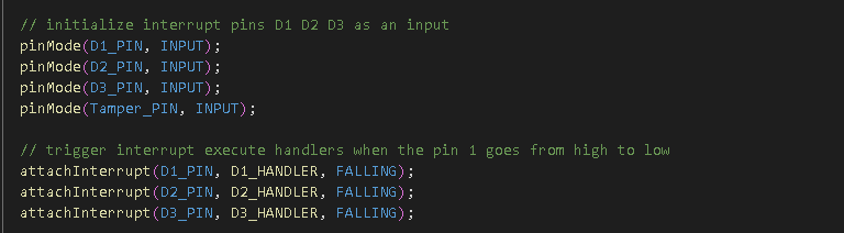
    // initialize interrupt pins D1 D2 D3 as an input with the internal pull-up resistor enabled
    pinMode(D1_PIN, INPUT);     //INPUT_PULLUP
    pinMode(D2_PIN, INPUT);     //INPUT_PULLUP
    pinMode(D3_PIN, INPUT);     //INPUT_PULLUP
    pinMode(Tamper_PIN, INPUT); //INPUT_PULLUP    
 
    // trigger interrupt execute handlers when the pin 1 goes from high to low
    attachInterrupt(D1_PIN, D1_HANDLER, FALLING);
    attachInterrupt(D2_PIN, D2_HANDLER, FALLING);
    attachInterrupt(D3_PIN, D3_HANDLER, FALLING);  

    for(int i=0;i<5;i++) {
      delay(3000);
      uplink_routine();
    }
}

void loop() {
  static uint64_t last = 0;
  static uint64_t elapsed;
  if ((elapsed = millis() - last) > (OTAA_PERIOD)) {
    uplink_routine();
    set_timer_sleep = true;
    last = millis();
  }

  if(set_timer_sleep) {
    delay(20);
    api.system.sleep.all(OTAA_PERIOD);
    set_timer_sleep = false;
  }
  else {
    api.system.sleep.all();
  }
}

Just a thought:

PA4, PA5 and PA6 are setup by RUI3 as SPI_NSS, SPI_CLK and SPI_MISO.

They should not be initialized unless there is a SPI.begin(), but did you try to use other pins like PA8, PA9, PB4, PB5 or PB2. These pins are assigned as GPIO’s or ADC pins.

With D1 held low, I’d expect ~ 3.3V / 1M → 3.3uA additional sleep current, for a total of ~ 8uA. It sounds like perhaps you have an on-chip pull-up resistor enabled on the GPIO you’re using, you’re seeing ~80uA more sleep current than expected, estimating 3.3V / 80uA → 41.25kOhm. I haven’t looked at the STM32WLE sheet for the on-chip pull-up value but that sounds totally sane and is probably your culprit. Check the config of pull-up on the pin. [Edit: looked it up, the on-chip pull-up is indeed 40k, see message below. Disable the pull-up]

Dana

OK - I can’t help myself, I looked it up, the typical STM32WLE5 pull-up resistor value is 40k. So you need to turn off the internal port pull-up:

40k seems typical for most if not all of the STM32 GPIOs.

1 Like

I understood. I tried several ways to uninhabit the Pull-Up and was unsuccessful:
In the file I found some functions and I got no result.

stm32wlxx_ll_pwr.h

LL_PWR_EnablePUPDCfg();
LL_PWR_DisableGPIOPullUp(LL_PWR_GPIO_A,LL_PWR_GPIO_BIT_4);
LL_PWR_DisableGPIOPullDown(LL_PWR_GPIO_A, LL_PWR_GPIO_BIT_4);
LL_PWR_DisablePUPDCfg();
Serial.printf(" Pull-Up %d “, LL_PWR_IsEnabledGPIOPullUp(LL_PWR_GPIO_A, LL_PWR_GPIO_BIT_4));
Serial.printf(” Pull-down %d ", LL_PWR_IsEnabledGPIOPullDown(LL_PWR_GPIO_A, LL_PWR_GPIO_BIT_4));

Even with a ‘0’ return, there was no change in the current behavior.

Could you help ?

How are you building your application for the RAK3172? Looks like you’re using STM32Cube with LL function generation for PWR?

LL_PWR_EnablePUPDCfg();
LL_PWR_DisableGPIOPullUp(LL_PWR_GPIO_A,LL_PWR_GPIO_BIT_4);
LL_PWR_DisableGPIOPullDown(LL_PWR_GPIO_A, LL_PWR_GPIO_BIT_4);
LL_PWR_DisablePUPDCfg();

I think the LL_PWR_DisablePUPDCfg() turns off - undoes - the settings you did above. It turns off the APC bit in PWR_CR3. For the per-bit settings to work, at least remove that.

What power-down mode are you putting the MCU in? I think the PUPDCfg hardware applies to the MCU in the Standy and Shutdown states; if I recall correctly the MCU is in STOP2 state when running the LoRaWAN stack (at least with the ST LoRaWAN port). So I suspect these bits don’t apply here. It’s the regular pull-up/down configuration for the GPIO bits you need to address.

If you’re using the LL code generation, I think that’s LL_GPIO_SetPinPull() you want to set. In fact, I think you want to initialize the GPIO pull mode regardless of what low power mode you use.

Hope that helps -
Dana

I’m using RUI3 API on Arduino. I didn’t find the function to disable Pull-Up in RUI3, I tried to find something in the STM32WLE files, because I didn’t have an option. I have no knowledge about this API. I still haven’t found a solution.

I’ll check out your tips and try something new.

Sounds like the RUI3 BSP isn’t turning-off the pull-up when you choose pinMode(…, INPUT) vs INPUT_PULLUP. Perhaps @beegee can check on this?

Cheers,
Dana

Have you tried manually calling LL_GPIO_SetPinPull() after setting-up the pin?

I don’t have the source codes for RUI3 at hand, so I made a quick check.

pinMode(WB_IO1, INPUT); ==> ~0.25V on the pin
pinMode(WB_IO1, INPUT_PULLUP); ==> ~3.29V on the pin

So RUI3 does disable the pullups as expected.

Run the same quick test on PA4, PA5 and PA6 which are setup by RUI3 as SPI_NSS, SPI_CLK and SPI_MISO.
They show the same values. ~.25V when setup as INPUT , ~3.29V when setup as INPUT_PULLUP.

#include <Arduino.h>

void setup()
{
	Serial.begin(115200);
	pinMode(WB_IO2, OUTPUT);
	digitalWrite(WB_IO2,HIGH);
}

void loop()
{
	pinMode(WB_SPI_CS, INPUT);
	pinMode(WB_SPI_CLK, INPUT);
	pinMode(WB_SPI_MISO, INPUT);
	Serial.println("PA4 INPUT");
	api.system.sleep.all(15000);
	pinMode(WB_SPI_CS, INPUT_PULLUP);
	pinMode(WB_SPI_CLK, INPUT_PULLUP);
	pinMode(WB_SPI_MISO, INPUT_PULLUP);
	Serial.println("PA4 INPUT_PULLUP");
	api.system.sleep.all(15000);
}
1 Like

Excellent test, Bernd - could you try adding the interrupt handler?

attachInterrupt(D1_PIN, D1_HANDLER, FALLING);

Possibly the enables the pull-up as a side-effect?

Thanks -
Dana

@danak6jq
Good idea and you unfortunately you are correct with the side-effect.
If I add the attachInterrupt() the voltage levels are up to 3.3V and setting pin mode “Input” without pullup doesn’t work.

Now I am not a STM32 expert and I don’t know if the pullup is automatically enabled if you setup a GPIO as interrupt source.

I tried both attachInterrupt(WB_SPI_CS, int_handler, FALLING); and attachInterrupt(WB_SPI_CS, int_handler, RISING); and the result is the same.

1 Like

Thank you @beegee for running the experiment - very useful.

On a couple of RAK3172s here running firmware generated from a fairly enhanced branch of danak6jq/RAK3172: Port of STM32WLxx example for RAK3172 (github.com) - bare metal on the STM32WLE5 using STM32Cube - I’ve configured pins as external interrupts (EXTI) and they do not have the internal pull-ups configured. Here’s the Cube-generated code:

  /*Configure GPIO pins : PAPin PAPin */
  GPIO_InitStruct.Pin = INPUT_IO6_Pin|INPUT_IO5_Pin;
  GPIO_InitStruct.Mode = GPIO_MODE_IT_RISING_FALLING;
  GPIO_InitStruct.Pull = GPIO_NOPULL;
  HAL_GPIO_Init(GPIOA, &GPIO_InitStruct);

These have a total of ~500k as a pull-up externally (as part of a level-shifter) and show ~6.3uA when pulling one down. So I’ll try a quick experiment and set the Pull mode to GPIO_PULLUP, build, flash, and…

Indeed, with the internal pull-up enabled on the GPIO, I see ~83uA when pulling one down. So the RUI3 attachInterrupt() appears to be explicitly turning-on the internal pull-up as a side-effect.

Thanks for doing the experiments there!

1 Like

Gents

We are just about the start a simple design based on the RAK3172 monitoring two reed relays

Is there any conclusion to the above high current problems when using standard RUI3 ?

Any workaround ?

Kind Regards
Paul Humphreys

Up. Any update about that ?

Any update on this issue??

Thanks in advance.

Any update about this issue ?