I am currently evaluating power optimization strategies for a design based on the RAK3172 (STM32WLE5CCU6) and would like to better understand how supply voltage influences current consumption in different operating modes.
Specifically, I am considering dynamically adjusting supply voltage depending on the operating state (sleep vs TX).
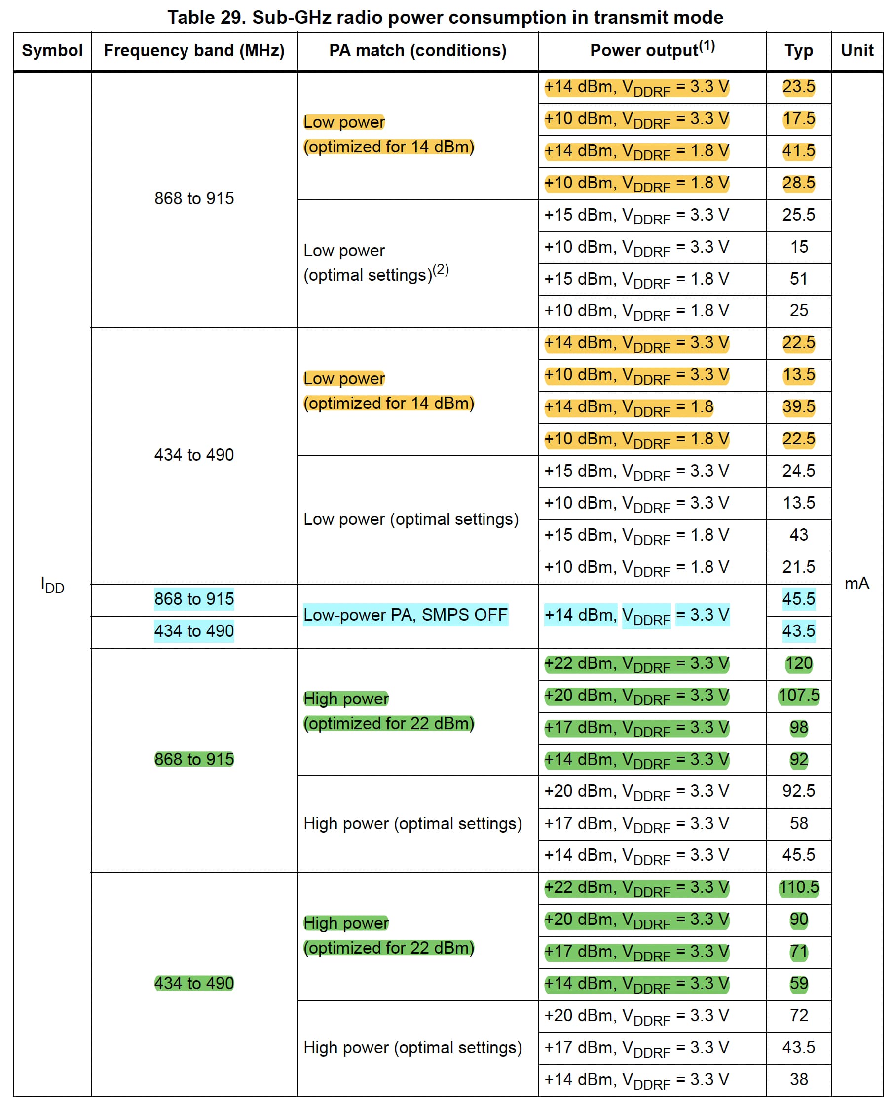
STM32WLE datasheet
The STM32WLE datasheet gives some useful information on this topic which might transfer to RAK3172.
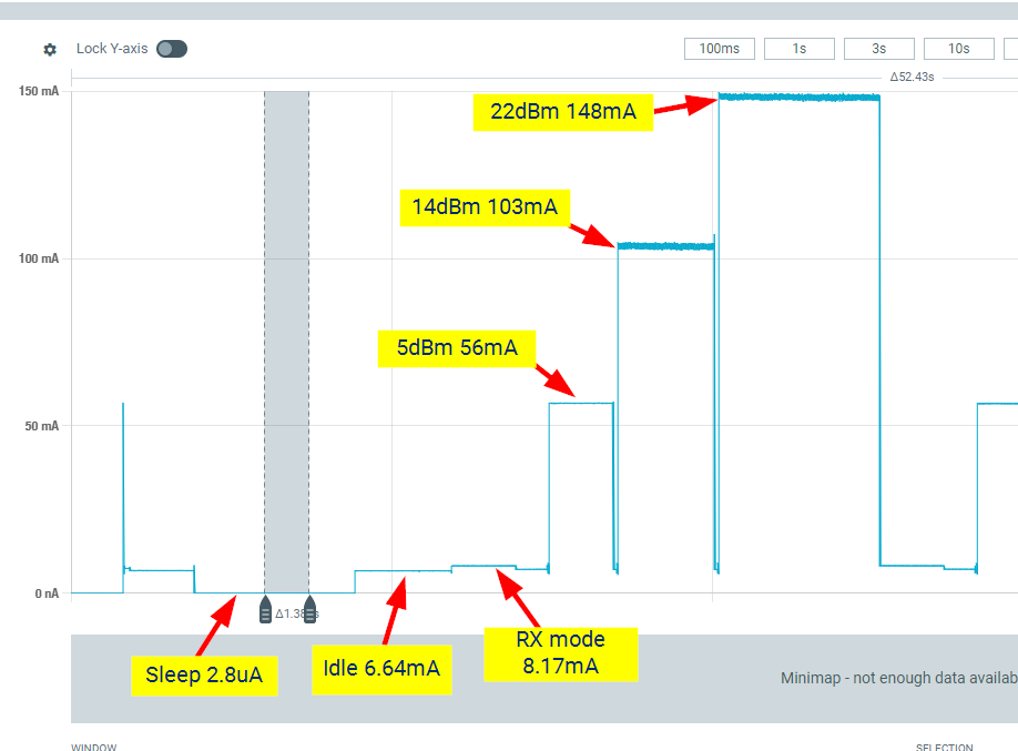
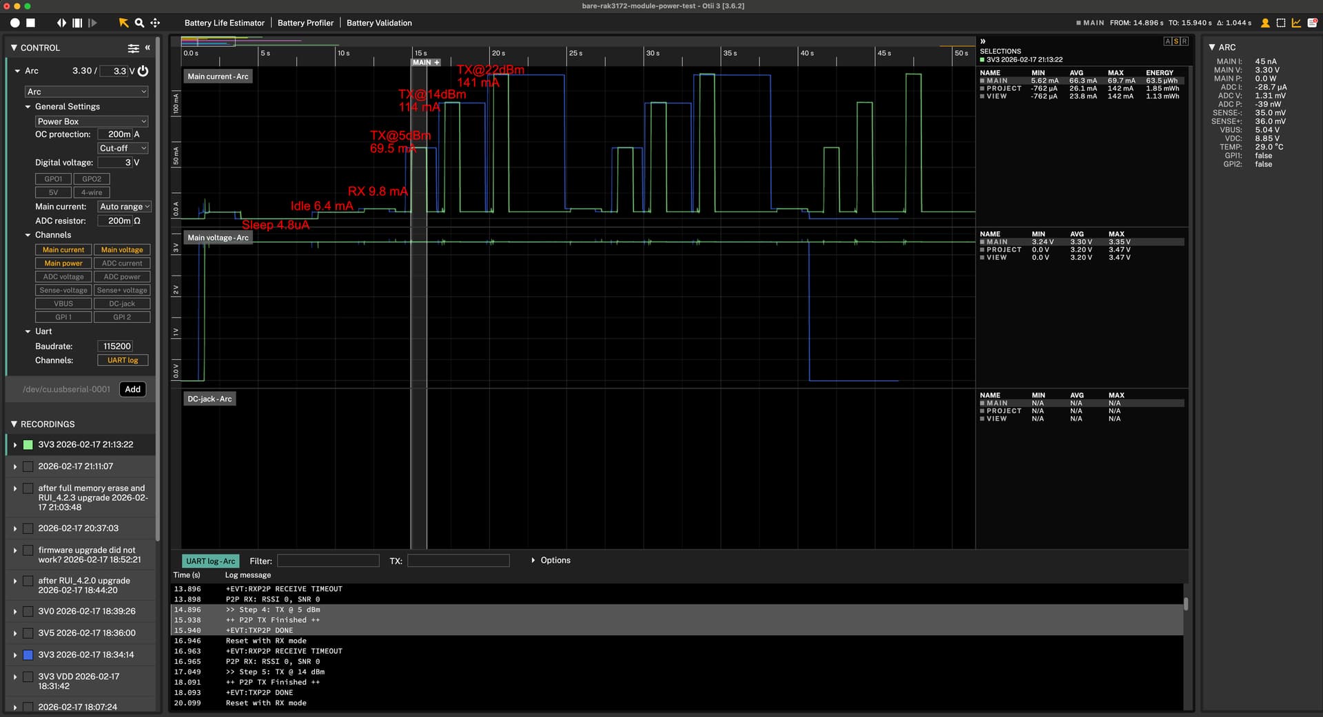
I am using a bare board with only the RAK3172. And measured different conditions, this is what I got running at 3.3V. I haven’t tested other voltage levels.
thank you for sharing this! Looking reasonable and thats very helpful.
However, I am wondering why does the curation of the TX peak increase with increased TX power? The duration should only be dependent on packet size and SF, right? Any chance you were using an old RUI version for this measurement like 4.0.6?
2. Do you use RAK3172 module or RAK3172-T? I used the one with TCXO.
I tested with the Firmware Version: RUI_4.0.6_RAK3172-T that was shipped on the modules I bought and got the same extending length TX durations. Additionally, I don’t see the “++ P2P TX Finished ++” messages in the logs.
With Firmware Version: RUI_4.2.3_RAK3172-T I do not get these anymore.
Besides that I get the following current readings at 3.3V
State
Carl
Mine
Sleep
2.8 µA
4.8 µA
Idle
6.64 mA
6.4 mA
RX mode
8.17 mA
9.8 mA
TX @ 5 dBm
56 mA
69.5 mA
TX @ 14 dBm
103 mA
114 mA
TX @ 22 dBm
148 mA
141 mA
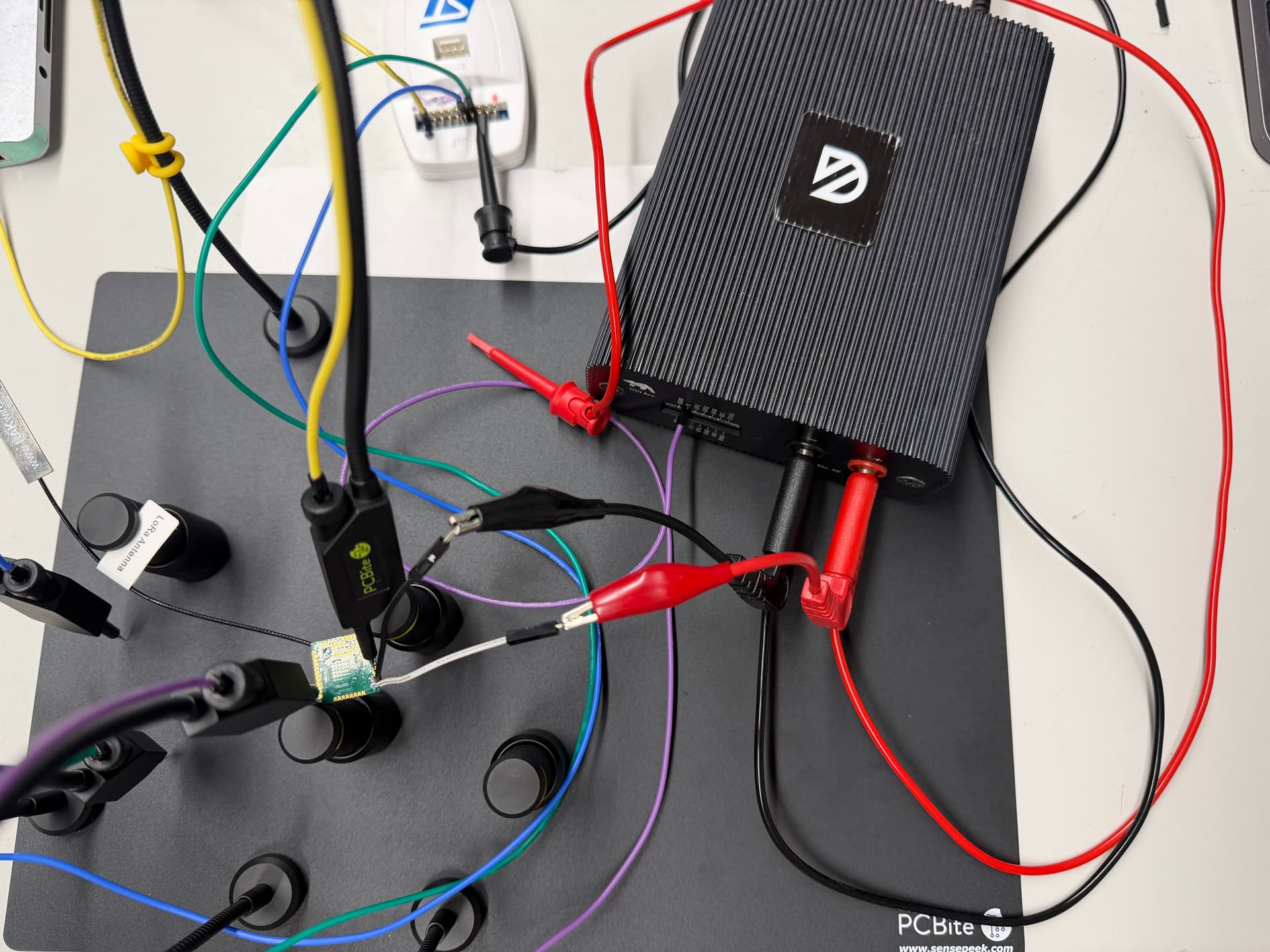
This is my setup
Otii Arc connected with 10cm long cables to the RAK3172T module. UART2-TXO connected to the Otii with the purple PCBite. RST has 10k pull-up to 3V3 and BOOT is pulled to GND with the yellow PCBite.
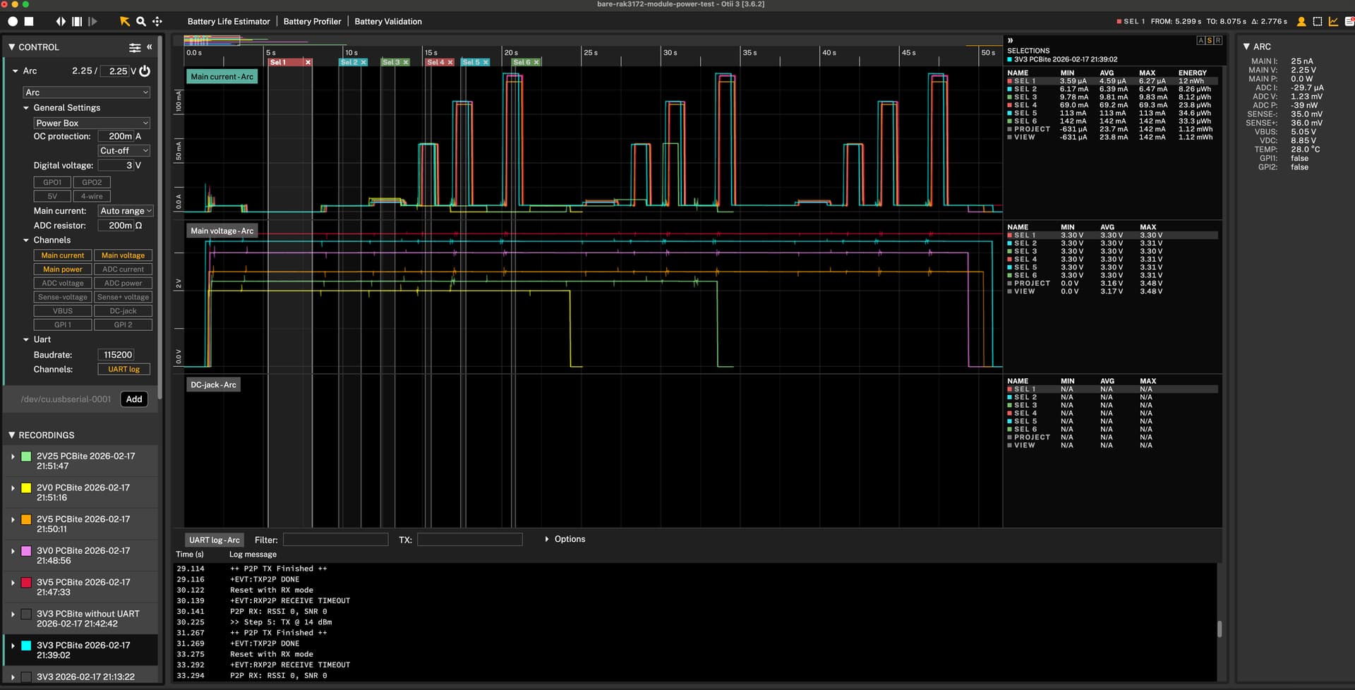
Coming back to the original question of voltage scaling current consumption I tested six voltages from 2.0V to 3.5V.
State / VDD
2.0 V
2.25 V
2.5 V
3.0 V
3.3 V
3.5 V
Sleep
4.24 µA
4.22 µA
4.43 µA
4.66 µA
4.59 µA
4.68 µA
Idle
6.14 mA
6.21 mA
6.27 mA
6.35 mA
6.39 mA
6.42 mA
RX
13.9 mA
12.6 mA
11.7 mA
10.4 mA
9.81 mA
9.48 mA
TX 5 dBm
board crashed
70.1 mA
69.8 mA
69.4 mA
69.2 mA
68.9 mA
TX 14 dBm
board crashed
board crashed
110 mA
113 mA
113 mA
113 mA
TX 22 dBm
board crashed
board crashed
133 mA
139 mA
142 mA
140 mA
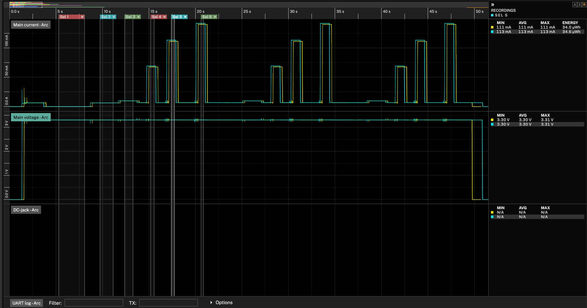
Interpretation of Measurements
There is no voltage dependent current consumption for TX. Voltages below 2.5V make the board crash at higher powers.
RX current increases with decreased supply voltage.
Sleep current is higher than expected (should be around 1-2 uA and not 4.5uA). It does decrease slightly with decreased supply voltage. Same for Idle current.
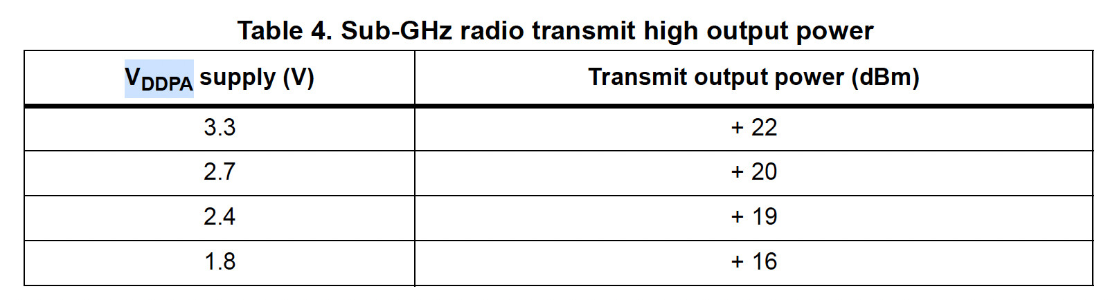
I would assume that the actual output power for 22dBm is decreased with supply voltages below 3.3V, since the STM32WLE datasheet specifies says so in Table 4.
I noticed little to no differences in sleep and idle currents between 2 modules that I tested.
The RF currents vary slightly with RX ±0.2 mA and TX ±2mA.
I don’t think there is any good reason to include voltage scaling just because of RX/TX power consumption. However, for effective sleep or idle power consumption, there is an advantage to keep the module at 2.0V since the sleep power is just 8.5 uW compared to 15 uW at 3.3V and idle power is 12.3 mW compared to 21 mW.
I will look into RAK3172-SIP as you suggested @carlrowan