Dear all,
I could not find the LoRaWAN MAC version of the 4260 in the datasheet.
Also, what are the regional parameters, for example with MAC1.0.2, is it PHY REV A or B?
Cheers
Welcome to forum @HansDieter12345 
Are you using the Microchip LoRaWAN SDK? It is based on LoRaWAN specs 1.0.2.
I will think forward. If are having issues connecting to the network server on both PHY REV A and REV B, probably your issue is not related on that. You can give more info why you ask and we will try to help 
If you don’t use the right version, bad things happen, not kittens or puppies being harmed, but still not good.
If you search the TTN forum you’ll find a number of long threads on this with some ranting by one of the moderators (@descartes) who can’t cope with people not reading the release notes but then being a bit nicer because Microchip do a jolly good job of hiding the actual version of MLS you are compiling against.
TL;DR - the latest version of MLS is 1_0_P_5 which is LoRaWAN v1.0.4 using regional parameters 1.0.2rB.
The descartes chap strongly recommends that you use ABP for development and install the TTS CLI tool so you can manage OTAA connections because MLS is highly compliant (and certified) and TTS is highly compliant, so you will run headlong in to a DevNonce reuse issue if you hammer away with OTAA. There are no problems if you are deploying, just a constant series of joins will go badly wrong very quickly - puppies may even be harmed, so just don’t do it.
1 Like
Thanks for sharing the update MLS version. I haven’t touch it for a while.
I saw before a long thread in TTN forum about the ATMSAM34 discussing about LoRaWAN v1.1 with devnonce now starting from zero. I am not sure if that is the same case with LoRaWAN v1.0.4.
DevNonce nonsense comes in with v1.0.4, so CLI commands on standby if you are using TTS CE!
Hi,
I am using Arduino-LMIC (GitHub - mcci-catena/arduino-lmic: LoraWAN-MAC-in-C library, adapted to run under the Arduino environment), so not the Microchip LoRaWAN SDK. My config looks like this:
const lmic_pinmap lmic_pins = {
    .nss = 29,
    .rxtx = 41,
    .rst = 33,
    .dio = {34, 35, LMIC_UNUSED_PIN},
    .rxtx_rx_active = 1,
    .rssi_cal = 0,
    .spi_freq = 8000000,
};
Does this look like it makes sense? 'Cause the documentation from Atmel is abysmal (Pin out, anyone?) and the Docs from RAK leave some mappings to be desired.
Currently, I have trouble getting anything of the ground, i.e. stuck with sending an initial frame. Using ABP in EU_868.
Also, SWD via JTAGICE3 does not work (always comes back with the “No device detected. Error 4109”), but that will be a problem for a different time.
Don’t know, it never occurred to me to take a certified device and use it with the Arduino eco-system. I don’t think Microchip were thinking along those lines either and probably not RAK for this module.
There is the BastWAN device which RAK sell that uses the SAMR34 and Arduino code base. That may provide pointers on configuration. As would setting the debug level to 1 or 2 to get more feedback.
But LMIC does report a radio error quite obviously when it first tries, so I’d hazard a guess at the pin settings being OK.
PS, you asked at the start what the LoRaMAC for the RAK4260 was. Well as you’re using MCCI LMIC, it’s you that’s bringing the LoRaMAC to the party.
I’m not 100% sure what v3.3.0 is, I was using v1.0.2 but I know that v4.0.0 is definitely v1.0.3 which is working a treat for me on one of my, cough, cough, hand built devices. Don’t worry RAK, not for actual device deployment; testing, throwaway and canary use only.
Hi @HansDieter12345 , it is my first time to see someone using LMIC for RAK4260 or ATSAM34 itself.
For all the pinouts you need, all the schematics are here - https://downloads.rakwireless.com/LoRa/RAK4260/Hardware-Specification/
Btw, the quick way on using RAK4260 in Arduino platform is via Bastwan as Nick suggested. It is not using LMIC though but Beelan LoRaWAN library.
Ah, didn’t realise. Not tried that ever but I’ve met the chap from Ideetron on which it’s based.
I believe it’s mostly compliant but with no clarity on it’s ability to process MAC commands - to which end many up to date Network Servers, particularly TTS as a few have discovered, will blitz the nearest gateway with many attempts to set up all sorts of things, many of which we didn’t realise existed until now!
So YMMV with regard to implementation on some networks. Just giving you heads up.
Personally, apart from having to use a Windows machine, I don’t have much issue with the Microchip Studio and the SAMR34 code base - I certainly find it easier to navigate than the STM32 / LoRa-node code base.
Sorry for jumping onto this train as well.
The last days I was running our RAK4260 EVB with the Arduino bootloader. I got it to work with the LMIC library, at least on AS923 and Chirpstack server, but I had problems with EU868. The OTAA joins fails all the time. I got it to work with ResIoT, but only if I force Join accept to be sent in RX2 window.
For the library pinout, this is my setting:
// Pin mapping for RAK4260 LoRa
const lmic_pinmap lmic_pins = {
  .nss = 29,
  .rxtx = 41,
  .rst = 33,
  .dio = {34, 35, 36},
  .rxtx_rx_active = true,
  .rssi_cal = 10,              // LBT cal for the Adafruit Feather M0 LoRa, in dB
  .spi_freq = 8000000,
};
So, beside of DIO2, the same pin settings.
I tried the BeeWAN library, but I found it less reliable and a very limited region support.
By the way, for the LMIC library, I hope you read that // This EUI must be in little-endian format, so least-significant-byte first for both the App EUI and the Dev EUI, while the app key is in big-endian format.
1 Like
Sorry, development took a break!
My setup works now (I can send), but I still have some questions:
-
The Pinout: https://downloads.rakwireless.com/LoRa/RAK4260/Hardware-Specification/RAK4260_VB_Schematic_20190807.pdf mentions the pin
RXTXfor example. I know this is the name of the Pin (also in the R34 docs), but what is its ID/number? And the inverse question for Pins 34, 35, 36 (PB16, PA11, PA12) - what is their name in the Schematic? -
@beegee I am using the same pin layout as you did, but I do not understand why it works.
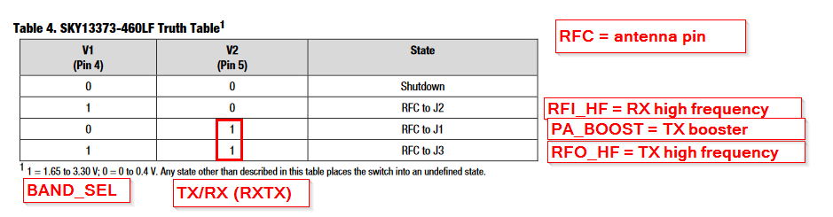
.rxtxis given as Pin 41, which is PA13 and also namedBAND_SEL- it connects to the Sky13373 V1. The pin specifically calledRXTXconnects to V2 on the Sky13373.
The documentation of the R34/R35 says: RXTX RX/TX switch control: High in TX. The config uses the inverse. Is this because of the switching logic of the Sky13373? Very confusing nonetheless.
Could you enlighten me?
Thank you for taking the time, I am very thankful for you input 
Welcome back @HansDieter12345
I didn’t touch the RAK4260 for a long time. Too excited with our new RAK3172 (STM32WL5)
(1)
RXTX => The datasheet of the SAM-R34 shows the pin, but no connection to the MCU itself, I can only guess it is connected to Semtech SX1272 inside the SAM-R34 and controlled by the SX1272 with one of its DIOx pins.
About the stamp modules pins 34, 35 and 36, in my schematics they are PB03 and GND
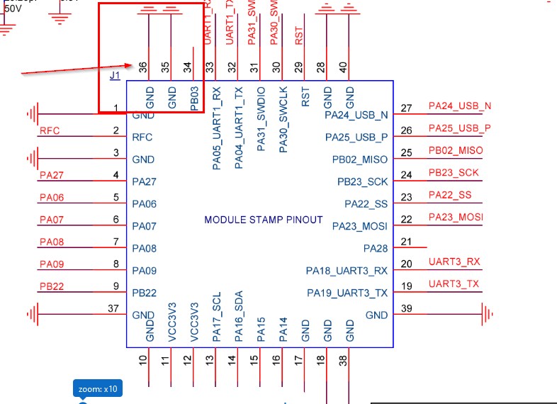
There are no PB16/PA11/PA12, even in the R34 datasheet.
(2)
Looking into the Sky13373 control table, TX/RX (our name) set to high will set the antenna switch to transmit. I didn’t look into the BeeWAN library into deep, but now I am wondering as well if there is some logic error in the setup.
But as I said, I didn’t touch the RAK4260 since we last talked. And I have it running as environment sensor all the time and it works.
Sorry, I was not clear on what I meant.
Regarding Pins, there is the numbering used by the RAK4260, and there is the one of the embedded SAM-R34.
.dio = {34, 35, 36},
This is the pinmap you and I both use, which configures these three pins for communicating to the SX127* - right? (If not, please correct me!)
These are pins of the SAM-R34, I know they are not available outside of the RAK4260, nor are they necessarily in the schematic (RAK4260_VB_Schematic_20190807.pdf), but somewhere in the datasheet of either the RAK4260 or the R34, there should be a clear mention of which pins are connected where and what they are actually called.
Every Pin in the R34 has a number associated to make use of it, and I am missing that number e.g. for the RXTX pin, so I do not know whether 41 is correct or not.
Same for the three DIO pins - I’d love to know how/where these are connected. IMHO, this is crucial information and its somehow missing.
Just to be clear on what I mean: RAK4260-Pin-4, also called PA27, is a pin I can use in my program. But to read or write from that Pin, I would use/refer to Pin 7, as this is the number this pin has internally in the R34. Or am I understanding something?
There are no PB16/PA11/PA12, even in the R34 datasheet.
I enumerated all valid pins to figure our their Port/Pin assignment, that is where this is from.
But as I said, I didn’t touch the RAK4260 since we last talked. And I have it running as environment sensor all the time and it works.
I am wondering whether it works, but not as it was intended to (using the wrong antenna), as I do not get the output signal strength I was expecting…
Ok, so you are looking for the GPIO’s that are inside the SAM-R34 coonected from the MCU to the SX1272.
If you look into the datasheet in chapter 5.2 you can find the Internal Multiplexed Signals
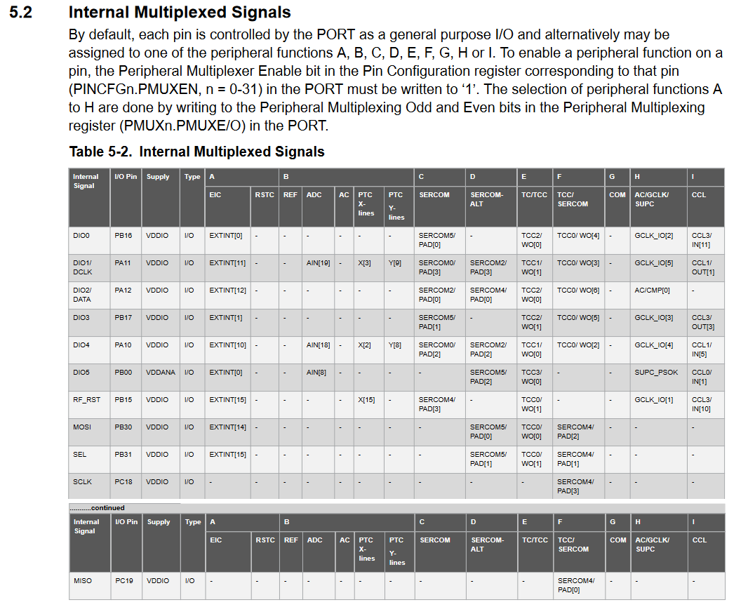
I guess that answers your question.
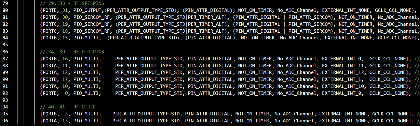
For the pin numbering, you have to look into the variant.cpp file in Arduino15\packages\electroniccats\hardware\samd\2.1.2\variants\bastwan, there you can find the “numbers” for all GPIO’s. E.g GPIO 5 is PA27
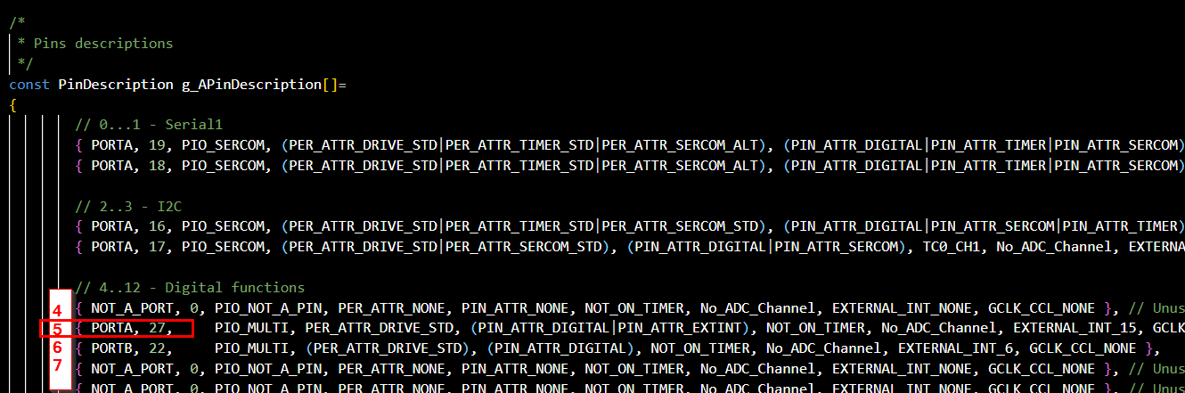
And there you find the pin numbers for the RF (==SX1272) as well: