Hi there!
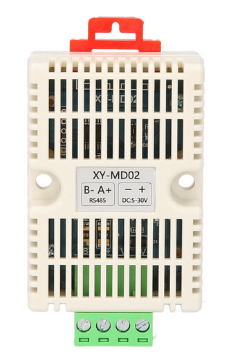
Im absolutely stuck while trying to read really simple data from a test modbus device, in this case a XY-MD02.
I got all messed up with libraries, examples and parameters…I tried modbus.h, modbusRTU, modbusRTUMaster, etc…
Some compile for RAK11300, some don’t even compile
The code I have now is the following:
#include <ModbusRTU.h>
ModbusRTU mb;

bool cb(Modbus::ResultCode event, uint16_t transactionId, void* data) {  // Callback to monitor errors
  if (event != Modbus::EX_SUCCESS) {
    Serial.print("Request result: 0x");
    Serial.println(event, HEX);
  }
  return true;
}

void setup() {
  /* IO2 HIGH  3V3_S ON */
  pinMode(WB_IO2, OUTPUT);
  digitalWrite(WB_IO2, HIGH);
  delay(500);

  Serial.begin(9600);
  Serial1.begin(9600);
  mb.begin(&Serial1);
  //mb.setBaudrate(19200);
  mb.master();
}

void loop() {
  uint16_t res[2]={0,0};
  if (!mb.slave()) {                   // Check if no transaction in progress
    mb.readIreg(1, 0x0001, res, 1, cb);  // Send Read Hreg from Modbus Server
    while (mb.slave()) {               // Check if transaction is active
      mb.task();
      delay(10);
    }
    Serial.print(res[0]);Serial.print(", ");
    Serial.println(res[1]);
  }
  delay(1000);
}```

With this Im trying to read input register at address 0x0001 at device 1, and also I tried readHreg (1,0x0101,res, 1, cb) with same result

In all these cases I get:
Request result: 0xE4
0, 0
If I change device id to another one like 2 or 150 I get E02, so this kind of lets me know there's something sending responses at ID=01

But I still get 0xE4 which means according to a website: SERVER_ID_MISMATCH // 0xE4, server ID mismatch between request and response but according to the code: [EX_TIMEOUT = 0xE4, // Custom. Operation not finished within reasonable time ]
So somehow if I use the right ID there's some response but not really understood, and if I use other ID I get 0xE2
I tried reversing A+ and B- on the RS485 wires and this gets worse as I get 0xE2 with the correct ID so this means I had it correct at the first time. And also the way it is now matches the printed A+ and B- on both

What else can I try?

Thanks!
Ok, before I try your suggestion, some updates.
I have a spare 4631 laying around so I programmed it with the basic RS485 receiver to debug the data flowing thru the 485 bus, and I jumpered wires from it to A and B in the other pair (11300 + device)
I get real and valid data flowing, both in the REQUEST and in the RESPONSE from the device:
01 04 00 01 00 01 60 0A <-This is the request from my 11300 asking for 1 input registers starting address 0x01 from device 01
01 04 02 00 FE 38 B0 <- And this is the response from device saying here I have 2 bytes 00FE which mean 25.4ºC
But on the 11300 side, I still keep getting the 0xE4 error code…
So it looks like the SEND is done correctly, the device is also understanding and responding correctly, but thje response is not being understood.
Im going to try to temporarily disable the CRC in the library to see if it changes anything
I tried your suggested library and example, with some minor changes to dump full buffer contect, and still same result. I keep the secondary rak4631 sniffing the 485 data
The request got sent correctly, asking for 1 register at 0x01 device 1. The response was sent in the correct format:
01 04 00 01 00 01 60 0A  (BTW I checked CRC with online calculator and its correct)
01 04 02 01 06 38 A2 (replies with 26.2ºC, CRC is OK too)
But on the master sketch I get this output:
Received 1

T 0.00 H 0.00

Buffer Full dump: 0:0:0:0:0:0:0:0:0:0:0:0:0:0:0:0:
Why isn’t the library decoding the response, both in my original sketch+library, neither with your sketch+library?
The only difference I see is that RAK11300 BSP is based on MBed, RAK4631 is based on FreeRTOS and my other test was on RAK4630 with RUI3. For me the RAK4631/RAK4630 both worked.
Never tried the RAK11300 with a real RS485 sensor.
Oh boy… what can I be doing wrong…
The builtin example “modbus-master-slave-for-arduino-master → simple slave” doesn’t even compile for RAK4631 with errors that lead to nothing rational…
c:/users/edu/appdata/local/arduino15/packages/rakwireless/tools/arm-none-eabi-gcc/9-2019q4/bin/../lib/gcc/arm-none-eabi/9.2.1/../../../../arm-none-eabi/bin/ld.exe: C:\Users\edu\AppData\Local\Temp\arduino\sketches\1169B7D68A4C5CCB3EAD207AABF29D03\sketch\simple_slave.ino.cpp.o: in function `setup':
C:\Users\edu\AppData\Local\Temp\.arduinoIDE-unsaved2024616-8220-1tj07tt.dn3rh\simple_slave/simple_slave.ino:26: undefined reference to `Adafruit_USBD_CDC::begin(unsigned long)'
c:/users/edu/appdata/local/arduino15/packages/rakwireless/tools/arm-none-eabi-gcc/9-2019q4/bin/../lib/gcc/arm-none-eabi/9.2.1/../../../../arm-none-eabi/bin/ld.exe: C:\Users\edu\AppData\Local\Temp\.arduinoIDE-unsaved2024616-8220-1tj07tt.dn3rh\simple_slave/simple_slave.ino:27: undefined reference to `Serial'
c:/users/edu/appdata/local/arduino15/packages/rakwireless/tools/arm-none-eabi-gcc/9-2019q4/bin/../lib/gcc/arm-none-eabi/9.2.1/../../../../arm-none-eabi/bin/ld.exe: C:\Users\edu\AppData\Local\Temp\arduino\sketches\1169B7D68A4C5CCB3EAD207AABF29D03\sketch\simple_slave.ino.cpp.o: in function `__static_initialization_and_destruction_0':
C:\Users\edu\AppData\Local\Temp\.arduinoIDE-unsaved2024616-8220-1tj07tt.dn3rh\simple_slave/simple_slave.ino:23: undefined reference to `Serial'
c:/users/edu/appdata/local/arduino15/packages/rakwireless/tools/arm-none-eabi-gcc/9-2019q4/bin/../lib/gcc/arm-none-eabi/9.2.1/../../../../arm-none-eabi/bin/ld.exe: C:\Users\edu\AppData\Local\Temp\arduino\sketches\1169B7D68A4C5CCB3EAD207AABF29D03/..\..\cores\rakwireless_nrf52_WisCoreRAK4631Board_softdevice_s140v6,debug_l0_1b225982fdd51c31c165c0badeabef51\core.a(Uart.cpp.o): in function `serialEventRun()':
C:\Users\edu\AppData\Local\Arduino15\packages\rakwireless\hardware\nrf52\1.3.3\cores\nRF5/Uart.cpp:27: undefined reference to `Adafruit_USBD_CDC::available()'
c:/users/edu/appdata/local/arduino15/packages/rakwireless/tools/arm-none-eabi-gcc/9-2019q4/bin/../lib/gcc/arm-none-eabi/9.2.1/../../../../arm-none-eabi/bin/ld.exe: C:\Users\edu\AppData\Local\Arduino15\packages\rakwireless\hardware\nrf52\1.3.3\cores\nRF5/Uart.cpp:30: undefined reference to `Serial'
collect2.exe: error: ld returned 1 exit status

exit status 1

Compilation error: exit status 1
Still investigating the sketch and library you provided before, I got to the point where it quits receiving in RUI3_ModbusRTU.cpp:
  int8_t i8state = getRxBuffer();

  if (i8state < 6)  // 7 was incorrect for functions 1 and 2 the smallest frame could be 6 bytes long
  {
    u8state = COM_IDLE;
    u16errCnt++;
    return i8state;
  }
I checked this variable which should hold the number of received bytes in the buffer, and needs at least 6 bytes to validate as receiving a real packet, and in my case it only holds i8state=3 so only 3 bytes received in the RxBuffer… Any hint on what could cause this?
The response I see in the 485 sniffer is complete:
01 04 04 01 13 01 B6 8B 9B
(meaning reply from device 1, 4 bytes payload, content 0113.->275=27.5ºC and 01B6->438=43,8% HR, and CRC=8B 9B)
Yes, that’s the device. I would say the reply is sent slowly and the last part of the message is received out of time os something but the fact is the sniffer shows both the request and the reply printed in a fraction of a second.
To be honest I don’t really need to connect to that specific device in my final application, and that’s only the cheapest device I could find to learn how to use modbus, but I need to communicate to a more complex device for water potabilization at a client’s facility that I can’t be testing, so I wanted to try this with this and then change device address and registers to communicate with the real device when our client allows us to access there, but I need to have 100% guaranteed to work before I get there
If you have a second RS485 module, you could try my ModBus Slave example code (works well on RAK4631).
That way you can find out if the RAK11310 + RS485 works.
Thanks, before I try it… some updates
I added some code to the library to be able to dump the temporary buffer that’s getting in the receive “poll” function after the query is sent.
I am sending the query: 01 04 00 01 00 02 20 0B
and the device is responding: 01 04 04 01 00 01 63 BB C1
Ok so the received buffer only has 3 bytes, that’s why the function I quoted above exists due to having less than 7 bytes, and the contents are 02 20 0B
which are not even from the reply but the trailing 3 bytes of the sent query…
Why is the POLL function seeing the last 3 bytes sent instead of the received info???
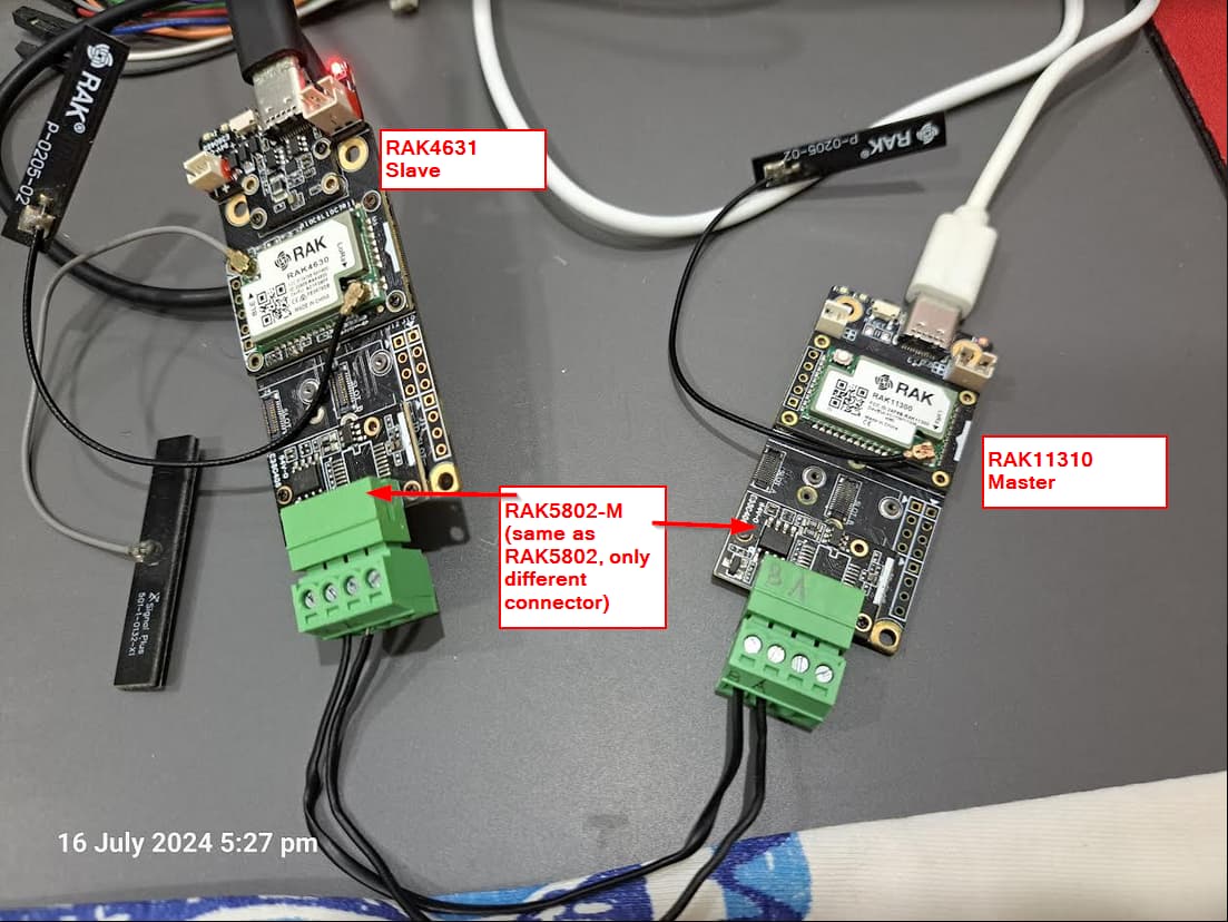
Also regarding the example you sent about using a second rs485… Yes I have another one. I believe I followed your same diagram:
One board 4631 + 5802 module, using the sketch + libraries included in your last comment
Another board with 11310 + 5802 using the sketch+ library in your comment that attached a photo of the connections.
Wire from A to A and from B to B
Started both serial monitors. Device 4631 doesn’t use Serial so it outputs nothing.
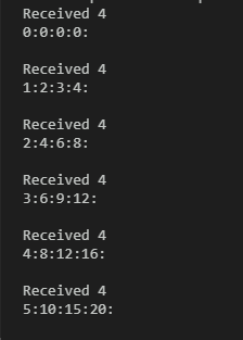
Device 11310 shows nothing received:
Received 4

0:0:0:0:

Received 4

0:0:0:0:
Tomorrow I will reseat the 5802 boards to see if the connection is loose but I dont believe so
Im running out of ideas… I used a different base board, same 11310 CPU, and different RAK5982 board (the one I was using for sniffing packets) and absolutely same result.
So at this point only a software issue in my computer could be the cause. I made sure I overwrote my .cpp and .h libraries with the ones you sent (as I had been adding some debug code in them) and still nothing. What else can I do to revert any changes? I can install Arduino from scratch but I don’t know if it preserves libraries somewhere
I got back to basic testing the bords and following the RAK5802 tutorial step by step.
Even trying the RS485 (not modbus) example for receiver and sender, while trying to compile the SENDER into the 4631 board, I get these errors:
WARNING: library ArduinoRS485 claims to run on samd, mbed_portenta, mbed_opta, mbed_nano, renesas_uno architecture(s) and may be incompatible with your current board which runs on nrf52 architecture(s).
c:/users/edu/appdata/local/arduino15/packages/rakwireless/tools/arm-none-eabi-gcc/9-2019q4/bin/../lib/gcc/arm-none-eabi/9.2.1/../../../../arm-none-eabi/bin/ld.exe: C:\Users\edu\AppData\Local\Temp\arduino\sketches\CE2BED26AB38B9735BF40453DB04FCAD\sketch\Sender.ino.cpp.o: in function `setup':
C:\Users\edu\AppData\Local\Temp\.arduinoIDE-unsaved2024618-17460-1qrlo5g.gf4q\Sender/Sender.ino:21: undefined reference to `Adafruit_USBD_CDC::begin(unsigned long)'
c:/users/edu/appdata/local/arduino15/packages/rakwireless/tools/arm-none-eabi-gcc/9-2019q4/bin/../lib/gcc/arm-none-eabi/9.2.1/../../../../arm-none-eabi/bin/ld.exe: C:\Users\edu\AppData\Local\Temp\.arduinoIDE-unsaved2024618-17460-1qrlo5g.gf4q\Sender/Sender.ino:22: undefined reference to `Adafruit_USBD_CDC::operator bool()'
c:/users/edu/appdata/local/arduino15/packages/rakwireless/tools/arm-none-eabi-gcc/9-2019q4/bin/../lib/gcc/arm-none-eabi/9.2.1/../../../../arm-none-eabi/bin/ld.exe: C:\Users\edu\AppData\Local\Temp\.arduinoIDE-unsaved2024618-17460-1qrlo5g.gf4q\Sender/Sender.ino:35: undefined reference to `Serial'
c:/users/edu/appdata/local/arduino15/packages/rakwireless/tools/arm-none-eabi-gcc/9-2019q4/bin/../lib/gcc/arm-none-eabi/9.2.1/../../../../arm-none-eabi/bin/ld.exe: C:\Users\edu\AppData\Local\Temp\arduino\sketches\CE2BED26AB38B9735BF40453DB04FCAD\sketch\Sender.ino.cpp.o: in function `loop':
C:\Users\edu\AppData\Local\Temp\.arduinoIDE-unsaved2024618-17460-1qrlo5g.gf4q\Sender/Sender.ino:57: undefined reference to `Serial'
c:/users/edu/appdata/local/arduino15/packages/rakwireless/tools/arm-none-eabi-gcc/9-2019q4/bin/../lib/gcc/arm-none-eabi/9.2.1/../../../../arm-none-eabi/bin/ld.exe: C:\Users\edu\AppData\Local\Temp\arduino\sketches\CE2BED26AB38B9735BF40453DB04FCAD/..\..\cores\rakwireless_nrf52_WisCoreRAK4631Board_softdevice_s140v6,debug_l0_1b225982fdd51c31c165c0badeabef51\core.a(Uart.cpp.o): in function `serialEventRun()':
C:\Users\edu\AppData\Local\Arduino15\packages\rakwireless\hardware\nrf52\1.3.3\cores\nRF5/Uart.cpp:27: undefined reference to `Adafruit_USBD_CDC::available()'
c:/users/edu/appdata/local/arduino15/packages/rakwireless/tools/arm-none-eabi-gcc/9-2019q4/bin/../lib/gcc/arm-none-eabi/9.2.1/../../../../arm-none-eabi/bin/ld.exe: C:\Users\edu\AppData\Local\Arduino15\packages\rakwireless\hardware\nrf52\1.3.3\cores\nRF5/Uart.cpp:30: undefined reference to `Serial'
collect2.exe: error: ld returned 1 exit status

exit status 1

Compilation error: exit status 1
Im lost as the mentioned functions (Adafruit_USBD_CDC) have absolutely nothing to do with what Im compiling…
I have all the RAK boards installed (ESP32, nRF, RP) and updated to latest version
Thanks
The Adafruit nRF52 BSP, which is base for the RAK4631 BSP requires you to add #include <Adafruit_TinyUSB.h>, but when you compile for other boards you have to remove it.
Ok at this point Im going to give up on this. It does compile now with the referred directives, but once uploaded it doesn’t get the packets sent from the “SENDER” so Im going to change the approach.
My goal is to read pH and Cl from a water treatment device, which provides these value both over RS485 bus and also thru 2 4-20mA ports. Im going to use 4-20mA now.
For this I will use a 4631 board with 19007 base. I need 2 analog inputs so if I use a 250 ohm resistor Im good to go. Now checking the documentation it looks like the 4631 has 3 analog inputs (AIN2-3-7) but the 19007 base board only exposes AIN1 (which is not using the same name as 4631…?)
Can you clarify this? I’ve also read something about one board that has one of the AIN’s taken by the batery measurement, is this the case?
Also I know there’s a 5801 board for 2x 4-20mA but my issue would be time for delivery as our client is now pushing a lot for delivery
On any WisBlock Base Board you have 3 analog inputs with the RAK4631
WB_A0 ==> connected to a resistor divider to read the battery voltage
WB_A1 ==> available
WB_IO4 ==> declared as GPIO, but can be used as analog input
If you use the RAK5801 4-20mA module, the analog inputs used are WB_A1 and WB_IO4 for both the RAK4631 and RAK11310.
If you cannot wait for the RAK5801, you need a RAK13002, which has all the pins available on pin headers.
Ok, no worries, I had already ordered a RAK5801 to a local supplier I’ve found so it will be here shortly
I know this is not your responsiblity but do you know if to be able to read 4-20mA from a device that provides the sensor, should MY DEVICE supply the 12VDC? Or does the sensor device provide 12VDC and the current limit?