# RAK3172: Same firmware, different sleep currents (120 µA / 15 µA / 5.6 µA). Why? How to fix? + Minimal 1.6 µA test

RAK3172: Same firmware, different sleep currents (120 µA / 15 µA / 5.6 µA). Why? How to fix? + Minimal 1.6 µA test

Setup

  • 3× RAK3172 modules, all flashed with the same program.
  • Battery powered. App sends a random number every 5 s.
  • Measured on Nordic PPK2.
  • Active TX current ≈ 120 mA on all three (consistent).
  • Sleep current is inconsistent: 120 µA, 15 µA, 5.6 µA.

Two questions

  1. Why such different sleep currents across identical code/hardware?
  2. Do you have a known-good code pattern to reliably reach ~1–2 µA so I can fold it into my app?

Hi @Prasanna ,

What hardware do you use? Also what firmware? Same FW with different current would lean me towards hardware related cause.

I can try on my own setup if you can share the code or hex file.

Hi Carlrowan,
sketch_sep2d.ino.hex (473.6 KB)
Yes—hardware: RAK3172 (3 units), firmware: RUI3 v4.2.1 on all three.

I’ve attached the HEX built from the same project I flashed to all modules. Please try it on your setup and let me know what sleep current you see.

My measurement setup (for context):

  • Power: battery-powered board, measured with Nordic PPK2 (Source mode).
  • App behavior: transmits a random number every 5 s (TX-only).
  • Observed currents (all same firmware/HEX):
    • Active TX: ~120 mA (all three, consistent)
    • Sleep: 120 µA (Unit A), 15 µA (Unit B), 5.6 µA (Unit C)

If you need the .ino/source as well, I can share that too. Thanks for checking—eager to hear your results and any pointers!

Hi @Prasanna ,

I uploaded your hex. I cannot send AT commands to configure an OTAA join. Maybe just send me code then I’ll recompile it.

ok. i will upload the code developed in arduino ide. this code only sends data every 5s once, remaining time is in sleep mode. i achieved 5.5uA from the 120uA by removing i2c pull up resistor. but some of the gpio are still enable and give 3.3v . pl check the code and guide mw which command is su
RAK_SleepTime_pgm.ino (2.1 KB)
itable

Hi @Prasanna ,

I was able to run your code. I got less than 3uA on two of my RAK3172 boards.

To do this, send these two AT commands:

AT+LPM=1
AT+LPMLVL=2

This will not allow you to use UART1 for waking up which is fine since you are not using UART1 anyway in your code.

My circuit is bare RAK3172 without anything connected. Just Nordic PPK2 in source mode 3.3v as well just like you do.

Nevertheless, there could be some leakage in your circuit which you have to check in case you cannot go lower than 5uA.

Here’s my measurement.

ok thanks for your information. If i connect i2c pull up resistor no circuit sensor or circuit connected, Again it showing 120uA. I did pinMode(PA11, INPUT);
pinMode(PA12, INPUT); in setup , then also same 120uA showing in Nordic PPk2. Any idea to overcome that

It can be that the leakage are from the I2C pull up. Initialize I2C wire and see if you can see improvement.

If you are not using I2C at this point, remove the pullup for now. It is impractical to fix those leakage if I2C sensor is not yet there as well as the I2C driver in the code.

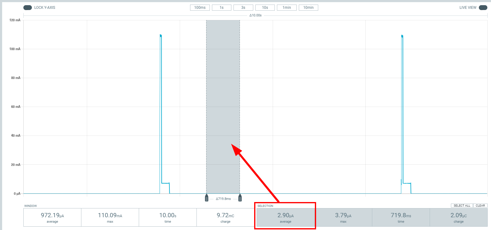
Thank you for your support. I removed I2C pullup resistor and also use AT+LPM & AT+LPMLVL=2 , can able to achieve 2.6uA in sleep Time. Once Again Thank you.

Hello @carlrowan

Good Day!

I have one doubt regarding programming the RAK3172 module. When I program it using UART with FTDI through STM32CubeProgrammer (with full chip erase before programming), some modules initially respond correctly, but after some time the response stops coming.

However, if I program the same modules via SWD using STM32CubeProgrammer, everything works well and the modules remain stable.

Has anyone else faced this issue? Are there any technical aspects, limitations, or steps I might be missing when using UART/bootloader programming compared to SWD?

Any guidance or clarification from the community would be very helpful.

HI @Prasanna ,

STM32CubeProgrammer via UART Bootloader of STM32 works everytime for me. There are cases that it will not work on some USB-Serial converter chips but as long as I am able to upload the .hex firmware, it will work ok. That is same when using STlinkV2 (original not clone). This is my personal experience.

I would suspect that the issue you have is not on uploading but on some other reason.

I am not sure if you plan to use LoRaWAN (I only see LoRa in your code) but we currently have issue on confirmed uplinks on v4.2.1 but already fixed in v4.2.2. Aside on this one, I am not aware on any issue on that RUI3 version you use.

Thank you for your support. So far, we have been working with LoRa P2P, and now we are moving into LoRaWAN development. If we have any clarifications or doubts during the process, I will update you.

Also, please keep me informed about the next version release.

At present, all our RAK modules are working well. If we encounter any modules with a no-response issue, I will share the screenshot with you for your reference.

Thank you once again.

1 Like