Hi there,
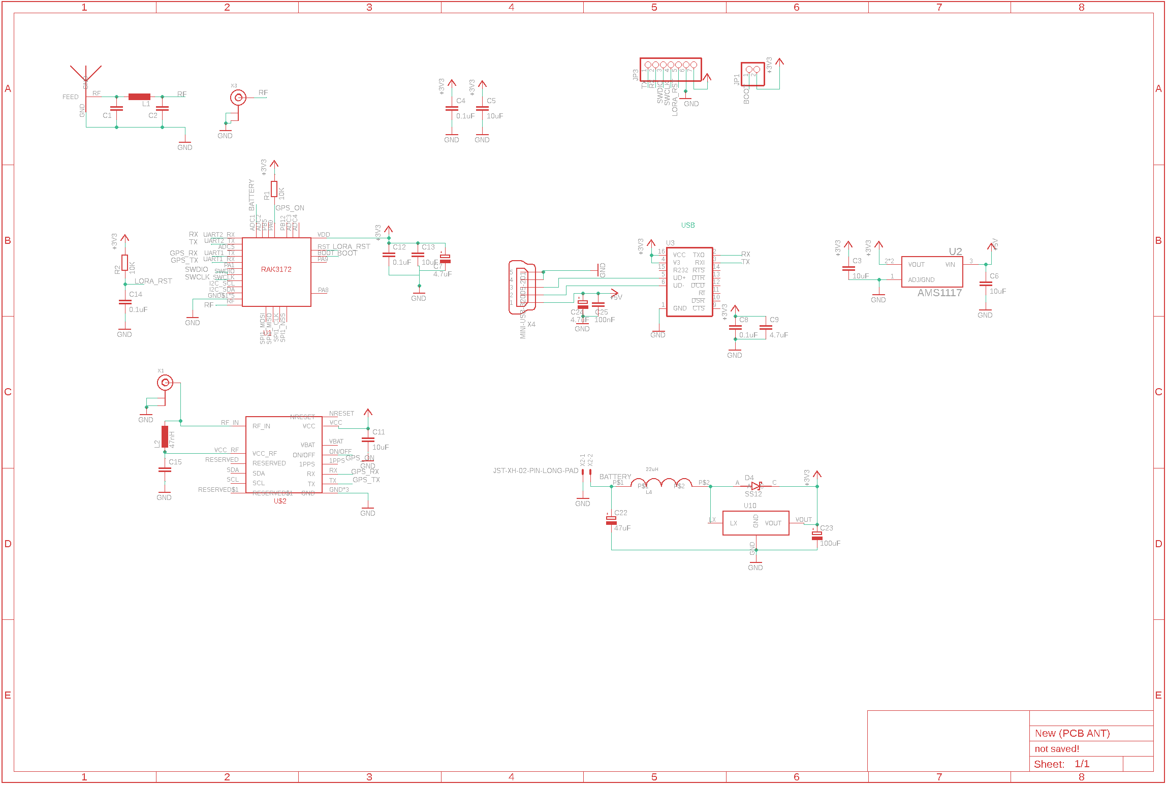
I posted this forum post a few months back as I was experiencing trouble with uploading Arduino IDE sketches to a RAK3172 on a custom PCB (schematic linked below, same as previous post). I swapped out the board for another one and the issues went away - Arduino BSP worked fine, Arduino sketch uploaded properly (quite a few times) and I was getting proper uplinks with TTN. I thought the issues I was facing with the Arduino BSP / Serial were isolated incidents due to a bad board.
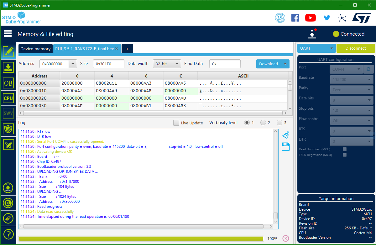
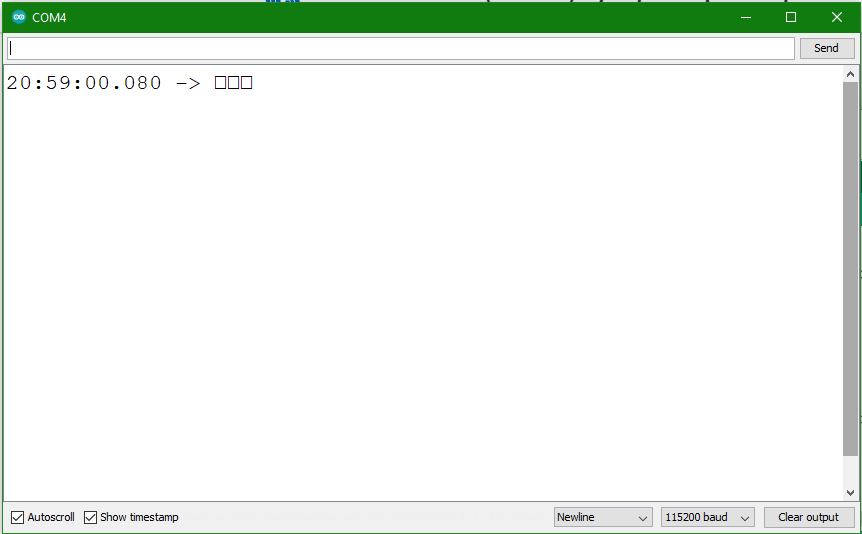
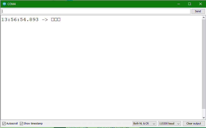
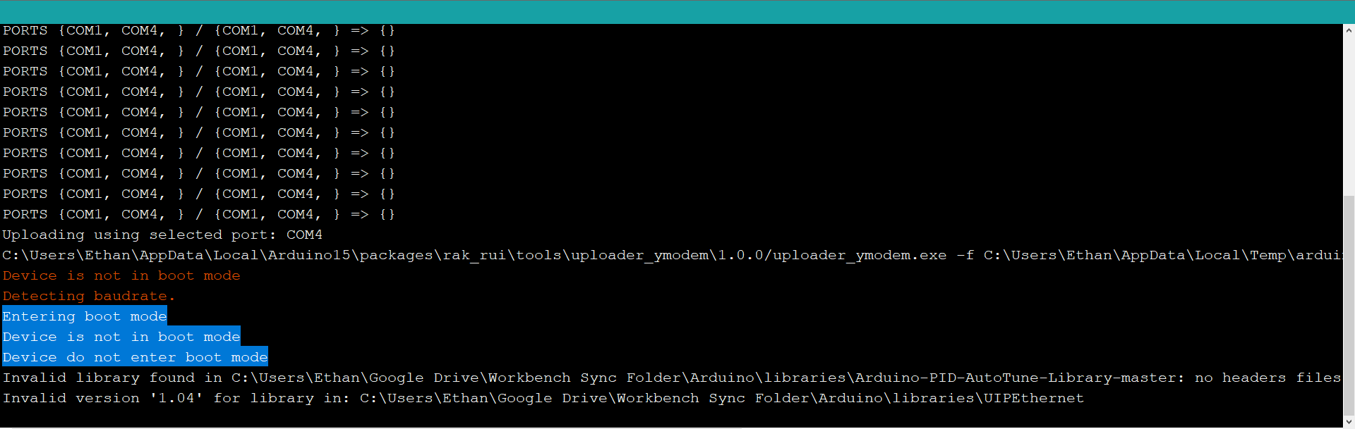
Fast forward to today and I was attempting to upload a modified version of my sketch (which I will attach below) and the Arduino BSP failed with “failed to get baudrate”. Not only that but the Serial is unresponsive to AT commands. However strangely enough reflashing the RAK3172 via the STM32CubeProgrammer as per this guide works every time (but still no Serial response to AT commands). This essentially puts me back in the same situation as my first post. As such, I felt it was worthwhile to reopen this issue as this seems to be a systematic problem. It seems to me that repeated flashing of the RAK3172 using the Arduino BSP is somehow messing up its internals and causing it to fail in the long-run (I lack experience in computer engineering to describe this precisely but you get the point).
What I have tried:
- Replacing the RAK3172 board entirely
- Bypassing the CH340C on my PCB and using an external FTDI adapter
- Reflashing using STM32CubeProgrammer with latest image (RAK3172-E_latest_final.hex)
- Putting the RAK3172 into boot mode first before uploading via ArduinoIDE
What I may try
- I purchased a RAK3272 breakout board and so I will observe if a similar thing happens to it since if it does it will rule out my custom PCB being the culprit.
- Remove the GPS module on UART1. Perhaps that is somehow conflicting with UART2?
Just throwing this out there so that anyone who experiences this same problem can chime in so that I can figure out if this problem is unique to my setup or a general problem.
Thanks.
Attachments:
#include <TinyGPS++.h>
TinyGPSPlus gps;

#define OTAA_BAND     (RAK_REGION_AS923)
#define OTAA_DEVEUI   {xxx}
#define OTAA_APPEUI   {xxx}
#define OTAA_APPKEY   {xxx} //keys removed for privacy reasons
#define OTAA_PERIOD   900000 //interval for device to wake up and send data to TTN
#define GPS_GRACE_PERIOD 5000 //grace period for GPS to get readings
uint8_t message[64] = { 0 };

uint64_t last = 0;

long latDec; //latDec = lattitude * 100000
long longDec; //longDec = longitude * 100000
uint8_t altDec = 0; //altDec = altitude * 1000
unsigned int battery; //battery = voltage * 100

boolean GPSFlag = true;
boolean batteryFlag = false;

uint8_t latIsNegative;
uint8_t longIsNegative;
uint8_t latArray[3] = {0, 0, 0};
uint8_t longArray[3] = {0, 0, 0};
uint8_t altArray[2] = {0, 0};

void recvCallback(SERVICE_LORA_RECEIVE_T * data)
{
  if (data->BufferSize > 0) {
    Serial.println("Something received!");
    for (int i = 0; i < data->BufferSize; i++) {
      Serial.printf("%x", data->Buffer[i]);
    }
    Serial.print("\r\n");
  }
}
void joinCallback(int32_t status)
{
  Serial.printf("Join status: %d\r\n", status);
}

void sendCallback(int32_t status)
{
  if (status == 0) {
    Serial.println("Successfully sent");
  } else {
    Serial.println("Sending failed");
  }
}

void setup() {
  // put your setup code here, to run once:
  Serial.begin(115200, RAK_DEFAULT_MODE);
  Serial1.begin(9600, RAK_CUSTOM_MODE);

  Serial.println("Ready");

  pinMode(PA0, OUTPUT);
  pinMode(PB4, INPUT);
  pinMode(PA8, INPUT_PULLUP);
  api.system.sleep.setup(RUI_WAKEUP_FALLING_EDGE, PA8);

  // OTAA Device EUI MSB first
  uint8_t node_device_eui[8] = OTAA_DEVEUI;
  // OTAA Application EUI MSB first
  uint8_t node_app_eui[8] = OTAA_APPEUI;
  // OTAA Application Key MSB first
  uint8_t node_app_key[16] = OTAA_APPKEY;
  if (!api.lorawan.appeui.set(node_app_eui, 8)) {
    Serial.printf("LoRaWan OTAA - set application EUI is incorrect! \r\n");
    return;
  }
  if (!api.lorawan.appkey.set(node_app_key, 16)) {
    Serial.printf("LoRaWan OTAA - set application key is incorrect! \r\n");
    return;
  }
  if (!api.lorawan.deui.set(node_device_eui, 8)) {
    Serial.printf("LoRaWan OTAA - set device EUI is incorrect! \r\n");
    return;
  }

  if (!api.lorawan.band.set(OTAA_BAND)) {
    Serial.printf("LoRaWan OTAA - set band is incorrect! \r\n");
    return;
  }
  if (!api.lorawan.deviceClass.set(RAK_LORA_CLASS_A)) {
    Serial.printf("LoRaWan OTAA - set device class is incorrect! \r\n");
    return;
  }
  if (!api.lorawan.njm.set(RAK_LORA_OTAA))  // Set the network join mode to OTAA
  {
    Serial.printf
    ("LoRaWan OTAA - set network join mode is incorrect! \r\n");
    return;
  }
  if (!api.lorawan.join())  // Join to Gateway
  {
    Serial.printf("LoRaWan OTAA - join fail! \r\n");
    return;
  }

  /** Wait for Join success */
  while (api.lorawan.njs.get() == 0) {
    Serial.print("Wait for LoRaWAN join...");
    api.lorawan.join();
    delay(10000);
  }

  if (!api.lorawan.adr.set(true)) {
    Serial.printf
    ("LoRaWan OTAA - set adaptive data rate is incorrect! \r\n");
    return;
  }
  if (!api.lorawan.rety.set(1)) {
    Serial.printf("LoRaWan OTAA - set retry times is incorrect! \r\n");
    return;
  }
  if (!api.lorawan.cfm.set(1)) {
    Serial.printf("LoRaWan OTAA - set confirm mode is incorrect! \r\n");
    return;
  }
  Serial.printf("Duty cycle is %s\r\n", api.lorawan.dcs.get() ? "ON" : "OFF"); // Check Duty Cycle status
  Serial.printf("Packet is %s\r\n", api.lorawan.cfm.get() ? "CONFIRMED" : "UNCONFIRMED"); // Check Confirm status
  uint8_t assigned_dev_addr[4] = { 0 };
  api.lorawan.daddr.get(assigned_dev_addr, 4);
  Serial.printf("Device Address is %02X%02X%02X%02X\r\n", assigned_dev_addr[0], assigned_dev_addr[1], assigned_dev_addr[2], assigned_dev_addr[3]);  // Check Device Address
  Serial.printf("Uplink period is %ums\r\n", OTAA_PERIOD);
  Serial.println("");
  api.lorawan.registerRecvCallback(recvCallback);
  api.lorawan.registerJoinCallback(joinCallback);
  api.lorawan.registerSendCallback(sendCallback);
}
void uplink_routine()
{
  /** Payload of Uplink */
  uint8_t data_len = 0;
  message[data_len++] = (uint8_t) latIsNegative;
  message[data_len++] = (uint8_t) latArray[0];
  message[data_len++] = (uint8_t) latArray[1];
  message[data_len++] = (uint8_t) latArray[2];
  message[data_len++] = (uint8_t) longIsNegative;
  message[data_len++] = (uint8_t) longArray[0];
  message[data_len++] = (uint8_t) longArray[1];
  message[data_len++] = (uint8_t) longArray[2];
  message[data_len++] = (uint8_t) altArray[0];
  message[data_len++] = (uint8_t) altArray[1];
  message[data_len++] = (uint8_t) battery;

  Serial.println("Data Packet:");
  for (int i = 0; i < data_len; i++) {
    Serial.printf("0x%02X ", message[i]);
  }

  /** Send the data package */
  if (api.lorawan.send(data_len, (uint8_t *) & message, 2, true, 1)) {
    Serial.println("Sending is requested");
  } else {
    Serial.println("Sending failed");
  }
}
void loop() {

     if(GPSFlag){
      GPSFlag = false;
      Serial.println("Turn the GPS ON");
      digitalWrite(PA0, LOW);
      Serial.println("GPS is ready");
      delay(7000); //wait 7s for the GPS to boot up
     }

    // Simulate the collection of data:
    //latDec = 12345678; //latDec = lattitude * 100000
    //longDec = 12345678; //longDec = longitude * 100000
    //altDec = 200 //altDec = altitude*1000
    //battery = 100; //battery = voltage / 3.3 * 100
    while (Serial1.available() > 0) {
      //char c = Serial1.read();
      //Serial.print(c);
      if (gps.encode(Serial1.read())) {
        if (gps.location.isValid()) {
          latDec = gps.location.lat() * 100000;
          longDec = gps.location.lng() * 100000;
          altDec = gps.altitude.meters()*1000;
          latIsNegative = (latDec < 0) ? 1 : 0;
          longIsNegative = (longDec < 0) ? 1 : 0;
          convert(abs(latDec), 1, 0);
          convert(abs(longDec), 2, 0);
          convert(altDec, 3, 0);
          Serial.println("GPS Coordinates: ");
          Serial.print("Lattitude: "); Serial.print(latDec); Serial.print(", Longitude: "); Serial.print(longDec); Serial.print(". Alt: "); Serial.print(altDec);

        } else {
          Serial.println("GPS is present but no valid coordinates!");
        }
      } else {
        Serial.println("No valid GPS found");
      }
    }
    if(batteryFlag){
      battery = analogRead(PB4) / 930 * 100;
      Serial.print("Battery: "); Serial.println(battery);
      batteryFlag = false;
    }


  if(millis()-last > OTAA_PERIOD + GPS_GRACE_PERIOD){
      last = millis();
      Serial.println("Turn the GPS OFF");
      digitalWrite(PA0, HIGH);
      Serial.print("Going to sleep for "); Serial.print(OTAA_PERIOD); Serial.println(" ms");
      GPSFlag = true;
      batteryFlag = true;
      uplink_routine();
      api.system.sleep.all(OTAA_PERIOD);
    }
}

void convert(long number, int flag, int index) {
  if (number >= 256) convert(round(number / 256), flag, index + 1);
  if (flag == 1) {
    latArray[index] = number % 256;
  } else if (flag == 2) {
    longArray[index] = number % 256;
  }else if(flag == 3){
    altArray[index] = number %256;
  }
}