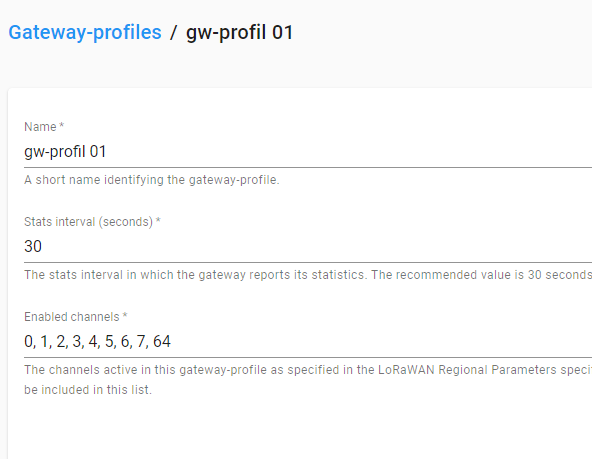
What is the channel settings in Chirpstack?
You selected AT+MASK=0001. Is your gateway and Chirpstack setup to same channel group (channel 0-7 for uplinks and channel 64 for downlinks)?
I tried using the sample code but when I joined the gateway it still failed, node and gateway antennas are installed, using the built-in antenna.
/***
 *  This example shows LoRaWan protocol joining the network in OTAA mode, class A, region EU868.
 *  Device will send uplink every 20 seconds.
***/

#define OTAA_PERIOD (20000)
/*************************************

   LoRaWAN band setting:
     RAK_REGION_EU433
     RAK_REGION_CN470
     RAK_REGION_RU864
     RAK_REGION_IN865
     RAK_REGION_EU868
     RAK_REGION_US915
     RAK_REGION_AU915
     RAK_REGION_KR920
     RAK_REGION_AS923

 *************************************/
#define OTAA_BAND (RAK_REGION_AU915)
#define OTAA_DEVEUI \
  { 0xAF, 0x90, 0xE9, 0x89, 0xFC, 0x97, 0x2F, 0x32 }
#define OTAA_APPEUI \
  { 0xDC, 0xA6, 0x32, 0xFF, 0xFE, 0x27, 0x09, 0xA0 }
#define OTAA_APPKEY \
  { 0xEA, 0xA1, 0x8D, 0xA6, 0x06, 0x47, 0x6D, 0x9D, 0x7E, 0x9A, 0x8E, 0x65, 0x26, 0x3C, 0x73, 0x14 }

/** Packet buffer for sending */
uint8_t collected_data[64] = { 0 };

uint16_t maskBuff = 0x0001;

void recvCallback(SERVICE_LORA_RECEIVE_T *data) {
  if (data->BufferSize > 0) {
    Serial.println("Something received!");
    for (int i = 0; i < data->BufferSize; i++) {
      Serial.printf("%x", data->Buffer[i]);
    }
    Serial.print("\r\n");
  }
}

void joinCallback(int32_t status) {
  Serial.printf("Join status: %d\r\n", status);
}

/*************************************
 * enum type for LoRa Event
    RAK_LORAMAC_STATUS_OK = 0,
    RAK_LORAMAC_STATUS_ERROR,
    RAK_LORAMAC_STATUS_TX_TIMEOUT,
    RAK_LORAMAC_STATUS_RX1_TIMEOUT,
    RAK_LORAMAC_STATUS_RX2_TIMEOUT,
    RAK_LORAMAC_STATUS_RX1_ERROR,
    RAK_LORAMAC_STATUS_RX2_ERROR,
    RAK_LORAMAC_STATUS_JOIN_FAIL,
    RAK_LORAMAC_STATUS_DOWNLINK_REPEATED,
    RAK_LORAMAC_STATUS_TX_DR_PAYLOAD_SIZE_ERROR,
    RAK_LORAMAC_STATUS_DOWNLINK_TOO_MANY_FRAMES_LOSS,
    RAK_LORAMAC_STATUS_ADDRESS_FAIL,
    RAK_LORAMAC_STATUS_MIC_FAIL,
    RAK_LORAMAC_STATUS_MULTICAST_FAIL,
    RAK_LORAMAC_STATUS_BEACON_LOCKED,
    RAK_LORAMAC_STATUS_BEACON_LOST,
    RAK_LORAMAC_STATUS_BEACON_NOT_FOUND,
 *************************************/

void sendCallback(int32_t status) {
  if (status == RAK_LORAMAC_STATUS_OK) {
    Serial.println("Successfully sent");
  } else {
    Serial.println("Sending failed");
  }
}

void setup() {
  Serial.begin(115200, RAK_AT_MODE);
  delay(2000);

  Serial.println("RAKwireless LoRaWan OTAA Example");
  Serial.println("------------------------------------------------------");

  if (api.lorawan.nwm.get() != 1) {
    Serial.printf("Set Node device work mode %s\r\n",
                  api.lorawan.nwm.set(1) ? "Success" : "Fail");
    api.system.reboot();
  }

  // OTAA Device EUI MSB first
  uint8_t node_device_eui[8] = OTAA_DEVEUI;
  // OTAA Application EUI MSB first
  uint8_t node_app_eui[8] = OTAA_APPEUI;
  // OTAA Application Key MSB first
  uint8_t node_app_key[16] = OTAA_APPKEY;

  if (!api.lorawan.appeui.set(node_app_eui, 8)) {
    Serial.printf("LoRaWan OTAA - set application EUI is incorrect! \r\n");
    return;
  }
  if (!api.lorawan.appkey.set(node_app_key, 16)) {
    Serial.printf("LoRaWan OTAA - set application key is incorrect! \r\n");
    return;
  }
  if (!api.lorawan.deui.set(node_device_eui, 8)) {
    Serial.printf("LoRaWan OTAA - set device EUI is incorrect! \r\n");
    return;
  }
  if (!api.lorawan.band.set(OTAA_BAND)) {
    Serial.printf("LoRaWan OTAA - set band is incorrect! \r\n");
    return;
  }
   Serial.printf("Set channel mask %s\r\n", api.lorawan.mask.set(&maskBuff) ? "Success" : "Fail");
  if (!api.lorawan.deviceClass.set(RAK_LORA_CLASS_A)) {
    Serial.printf("LoRaWan OTAA - set device class is incorrect! \r\n");
    return;
  }
  if (!api.lorawan.njm.set(RAK_LORA_OTAA))  // Set the network join mode to OTAA
  {
    Serial.printf("LoRaWan OTAA - set network join mode is incorrect! \r\n");
    return;
  }
  if (!api.lorawan.join())  // Join to Gateway
  {
    Serial.printf("LoRaWan OTAA - join fail! \r\n");
    return;
  }

  /** Wait for Join success */
  while (api.lorawan.njs.get() == 0) {
    Serial.print("Wait for LoRaWAN join...");
    api.lorawan.join();
    delay(10000);
  }

  if (!api.lorawan.adr.set(true)) {
    Serial.printf("LoRaWan OTAA - set adaptive data rate is incorrect! \r\n");
    return;
  }
  if (!api.lorawan.rety.set(1)) {
    Serial.printf("LoRaWan OTAA - set retry times is incorrect! \r\n");
    return;
  }
  if (!api.lorawan.cfm.set(1)) {
    Serial.printf("LoRaWan OTAA - set confirm mode is incorrect! \r\n");
    return;
  }

  /** Check LoRaWan Status*/
  Serial.printf("Duty cycle is %s\r\n", api.lorawan.dcs.get() ? "ON" : "OFF");             // Check Duty Cycle status
  Serial.printf("Packet is %s\r\n", api.lorawan.cfm.get() ? "CONFIRMED" : "UNCONFIRMED");  // Check Confirm status
  uint8_t assigned_dev_addr[4] = { 0 };
  api.lorawan.daddr.get(assigned_dev_addr, 4);
  Serial.printf("Device Address is %02X%02X%02X%02X\r\n", assigned_dev_addr[0], assigned_dev_addr[1], assigned_dev_addr[2], assigned_dev_addr[3]);  // Check Device Address
  Serial.printf("Uplink period is %ums\r\n", OTAA_PERIOD);
  Serial.println("");
  api.lorawan.registerRecvCallback(recvCallback);
  api.lorawan.registerJoinCallback(joinCallback);
  api.lorawan.registerSendCallback(sendCallback);
}

void uplink_routine() {
  /** Payload of Uplink */
  uint8_t data_len = 0;
  collected_data[data_len++] = (uint8_t)'t';
  collected_data[data_len++] = (uint8_t)'e';
  collected_data[data_len++] = (uint8_t)'s';
  collected_data[data_len++] = (uint8_t)'t';

  Serial.println("Data Packet:");
  for (int i = 0; i < data_len; i++) {
    Serial.printf("0x%02X ", collected_data[i]);
  }
  Serial.println("");

  /** Send the data package */
  if (api.lorawan.send(data_len, (uint8_t *)&collected_data, 2, true, 1)) {
    Serial.println("Sending is requested");
  } else {
    Serial.println("Sending failed");
  }
}

void loop() {
  static uint64_t last = 0;
  static uint64_t elapsed;

  if ((elapsed = millis() - last) > OTAA_PERIOD) {
    uplink_routine();

    last = millis();
  }
  //Serial.printf("Try sleep %ums..", OTAA_PERIOD);
  api.system.sleep.all(OTAA_PERIOD);
  //Serial.println("Wakeup..");
}
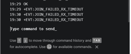
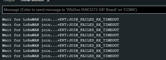
Wait for LoRaWAN join...+EVT:JOIN_FAILED_RX_TIMEOUT
Wait for LoRaWAN join...+EVT:JOIN_FAILED_RX_TIMEOUT
Wait for LoRaWAN join...+EVT:JOIN_FAILED_RX_TIMEOUT
Wait for LoRaWAN join...+EVT:JOIN_FAILED_RX_TIMEOUT
Wait for LoRaWAN join...+EVT:JOIN_FAILED_RX_TIMEOUT
Wait for LoRaWAN join...+EVT:JOIN_FAILED_RX_TIMEOUT
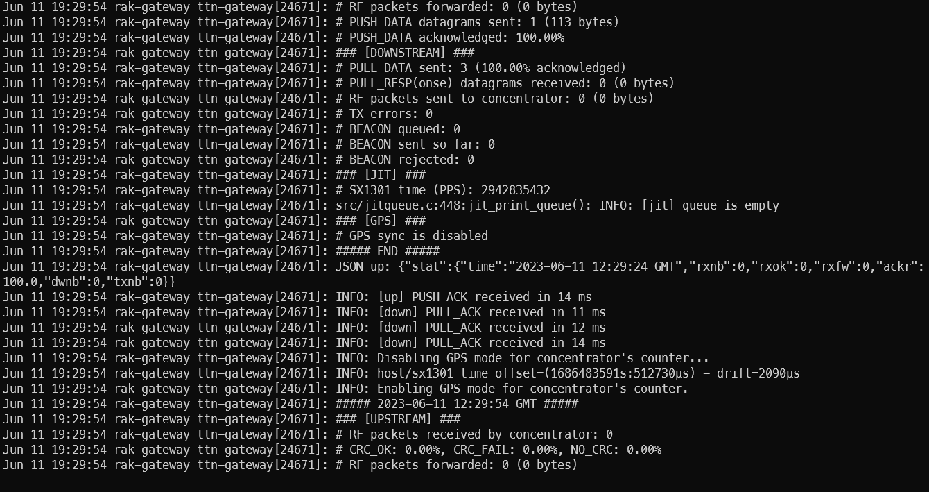
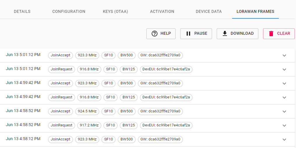
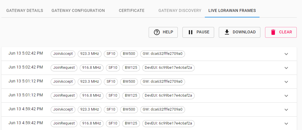
You can check the frequency that the RAK3172 is sending it’s join request and as well the frequencies it expects the join accept message. Check that these frequencies are matching with your settings in the gateway.
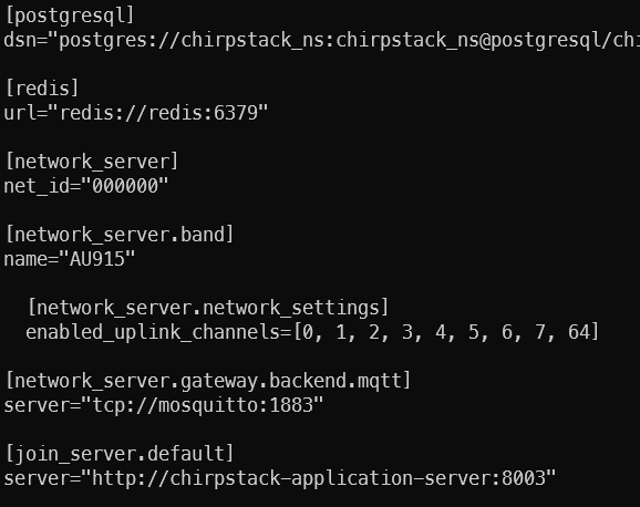
check again your settings on the gateway. The MQTT settings look different in my Chirpstack LoRaWAN server .toml file:
  # Backend defines the gateway backend settings.
  #
  # The gateway backend handles the communication with the gateway(s) part of
  # the LoRaWAN network.
  [network_server.gateway.backend]
  # Backend
  type="mqtt"


    # MQTT gateway backend settings.
    #
    # This is the backend communicating with the LoRa gateways over a MQTT broker.
    [network_server.gateway.backend.mqtt]
    # MQTT topic templates for the different MQTT topics.
    #
    # The meaning of these topics are documented at:
    # https://www.chirpstack.io/gateway-bridge/
    #
    # The default values match the default expected configuration of the
    # ChirpStack Gateway Bridge MQTT backend. Therefore only change these values when
    # absolutely needed.

    # Event topic template.
    event_topic="gateway/+/event/+"

    # Command topic template.
    #
    # Use:
    #   * "{{ .GatewayID }}" as an substitution for the LoRa gateway ID
    #   * "{{ .CommandType }}" as an substitution for the command type
    command_topic_template="gateway/{{ .GatewayID }}/command/{{ .CommandType }}"

    # MQTT server (e.g. scheme://host:port where scheme is tcp, ssl or ws)
    server="tcp://localhost:1883"
TX frequency and DR for the join request are correct, so I see no problem on the RAK3172.
My toml files will not help you much. My setup is for AS923-3 which is quite different from AU915.
But I can send them as PM (cannot attach such files here) and you can compare for differences.
I have received the configuration file, can you explain the values below in the chirpstack-gateway-bridge.toml file
  # Region.
  #
  # Please refer to the LoRaWAN Regional Parameters specification
  # for the complete list of common region names.
  region="AS923-3"

  # Minimal frequency (Hz).
  frequency_min=91660000

  # Maximum frequency (Hz).
  frequency_max=918000000
and the values below in the chirpstack-network-server.toml file.
rx2_frequency=916600000
    rx2_dr=2

    # enabled_uplink_channels=[0, 1, 2, 3, 4, 5, 6, 7, 8]
    enabled_uplink_channels=[0, 1]

    # Extra channel configuration.
    #
    # Use this for LoRaWAN regions where it is possible to extend the by default
    # available channels with additional channels (e.g. the EU band).
    # The first 5 channels will be configured as part of the OTAA join-response
    # (using the CFList field).
    # The other channels (or channel / data-rate changes) will be (re)configured
    # using the NewChannelReq mac-command.
    #
     [[network_server.network_settings.extra_channels]]
     frequency=917000000
     min_dr=0
     max_dr=5

     [[network_server.network_settings.extra_channels]]
     frequency=917200000
     min_dr=0
     max_dr=5

     [[network_server.network_settings.extra_channels]]
     frequency=917400000
     min_dr=0
     max_dr=5

     [[network_server.network_settings.extra_channels]]
     frequency=917600000
     min_dr=0
     max_dr=5

     [[network_server.network_settings.extra_channels]]
     frequency=917800000
     min_dr=0
     max_dr=5

     [[network_server.network_settings.extra_channels]]
     frequency=918000000
     min_dr=0
     max_dr=5
The configuration is different for AU915 (of course). I never setup Chirpstack for AU915, so some parts are just guessing:
For the first part
your region is of course “AU915”
min and max frequencies are 915200000 and 927800000 (AU915 has 64 possible channels)
For the second part
rx2 frequency and DR is 923.3 MHz / DR8
In your case (using subband 0), the enabled uplink channels should be [0, 1, 2, 3, 4, 5, 6, 7, 8] and you do not need the network_server.network_settings.extra_channels
AS923 is very different.
a) it has only 8 possible channels
b) join is only possible on two channels, the other 6 channels are assigned by the LoRaWAN server, that’s why it needs the network_server.network_settings.extra_channels
thank you very much @beegee
after testing many times with your suggestion, the result still fails.
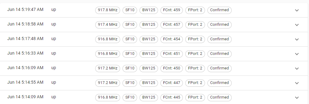
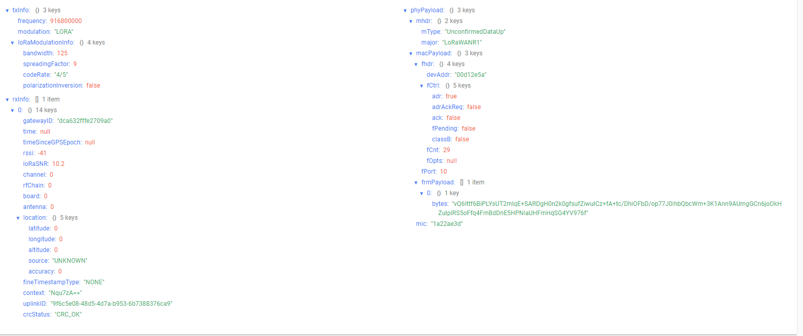
however the output in the data frame on the gateway and device like this
You are loosing packets.
Look at the FCnt values:
445 => 447 ==> 450 ==> 451 ==> 454 ==> 457 ==> 459
Every missing FCnt value is a packet that wasn’t received by the gateway.
How far (or close) is the RAK3127-SiP from the Gateway?
How is the connection between Gateway and the Chirpstack LNS? Are they on the same RPI?
What is your TX power settings. LoRaWAN has the weird setting that TX power 0 is the strongest and TX power 10 is the weakest.
If your RAK3172-SiP is very close to the gateway, you might want to try a lower TX value to avoid too strong signals that might over-saturate the RX part of the gateway.
Try to enhance the distance between the RAK3172 and the gateway. They are really close to each other for a long distance communication medium like LoRa.
You try as well to reduce the TX power on the RAK3172 with AT+TXP=5, which will reduce the power from 22dBm to 11dBm.
With having the two that close, you might even get it to work with AT+TXP=10
Thank you very much for the help that has been given.
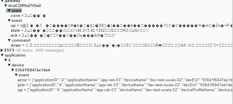
how can I get information related to RSSI and SNR data, I subscribe to data gateway data is still encrypted. Please provide information regarding this.