RAK3272-SiP and W5500 Ethernet controller

Hi all I’d like to go on starting from this thread
https://forum.rakwireless.com/t/how-to-use-spi-communication-with-rak3172/8022/7
but I open a specific thread for clarity.

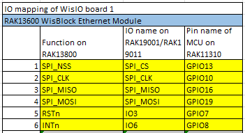
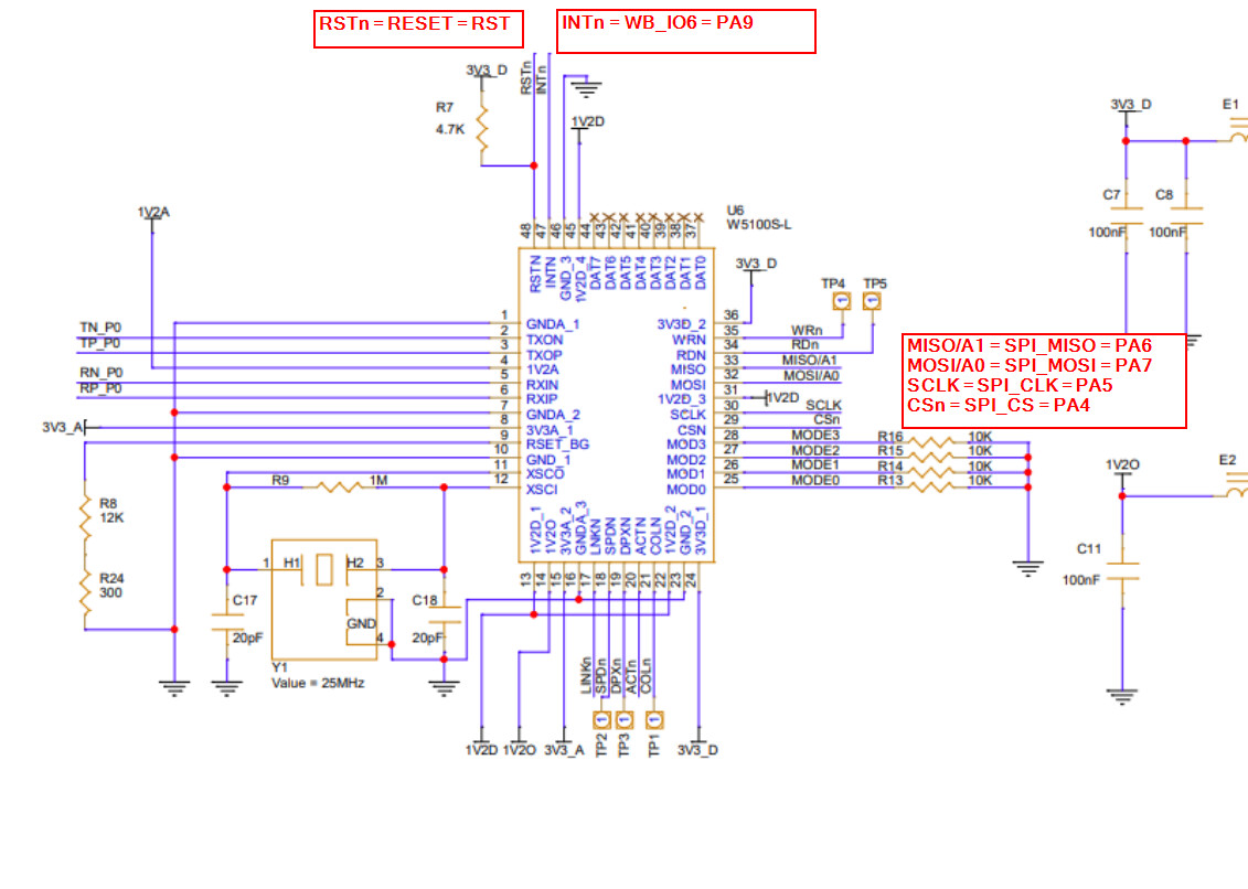
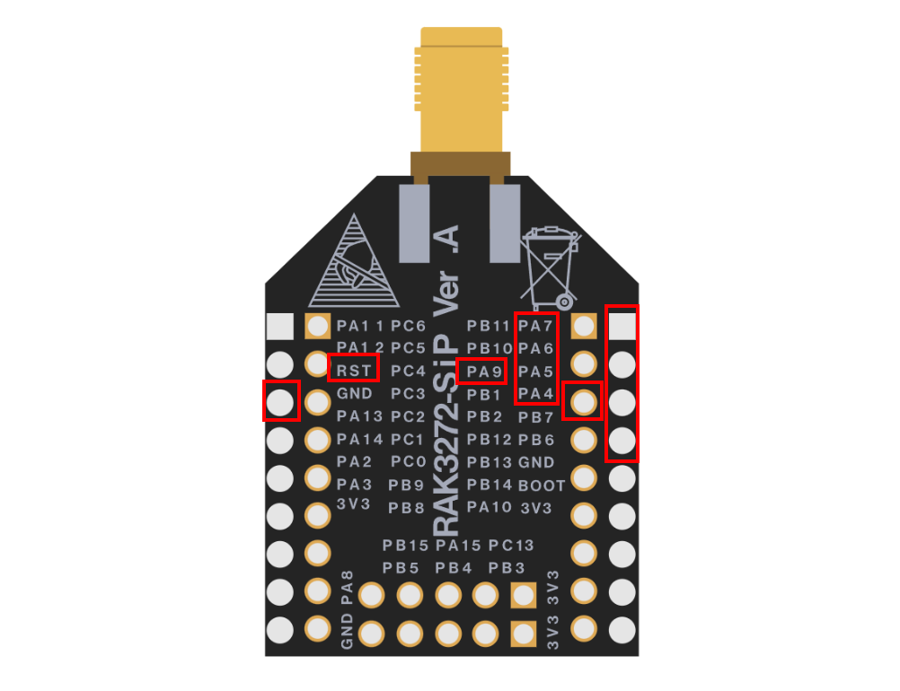
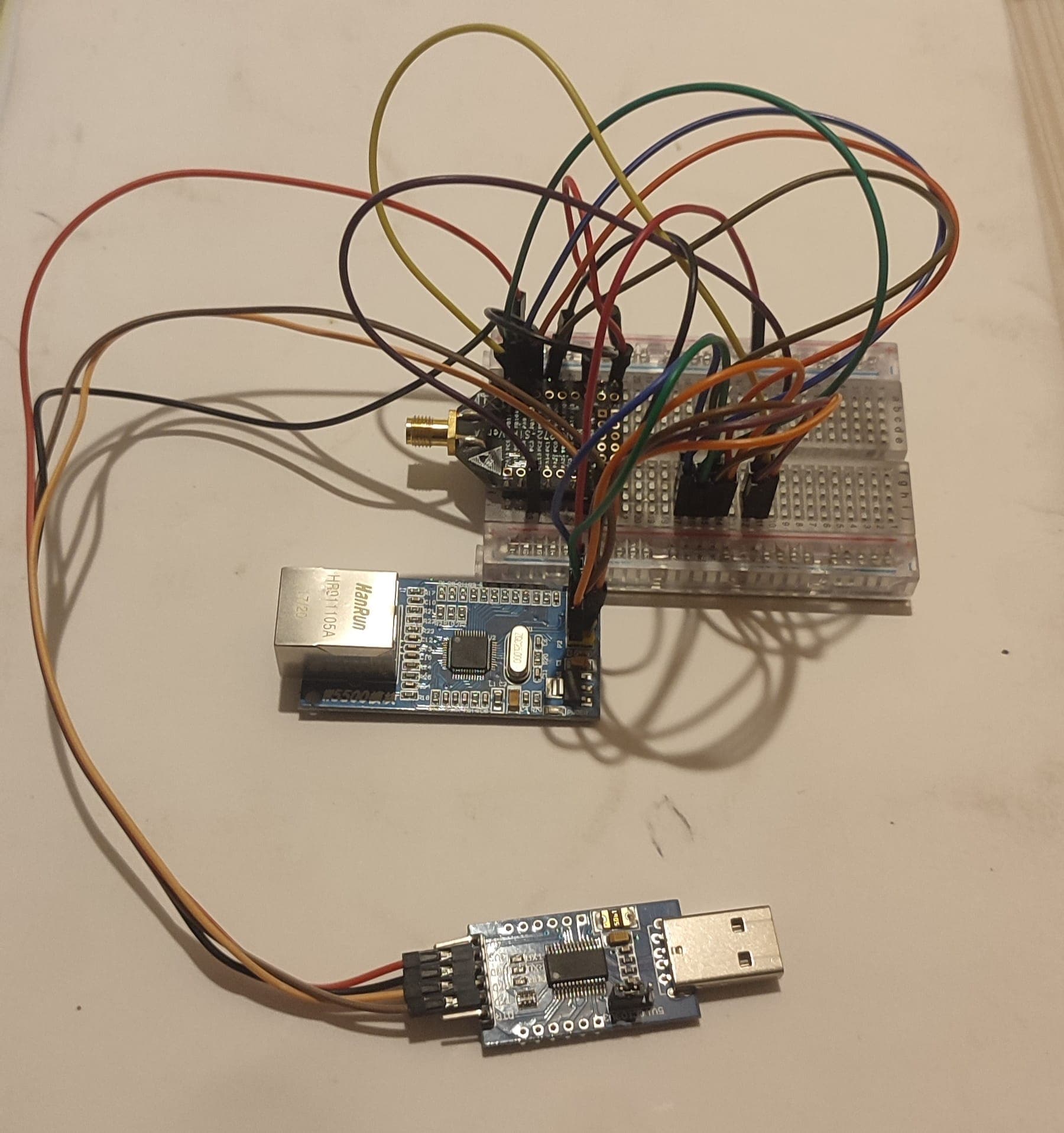
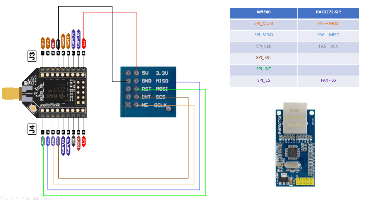
I’d like to use a W5500 eth controller connected to RAK3272-SiP to build a custom module able to manage 2 communication channels.

I’ve done some test using the RAK13800_W5100S library with partial success:
The example sketch is able to detect the presence of the module, giving the error “no module” if it is not present, but hangs after the “Ethernet.begin” call both in DHCP or fixed IP mode.

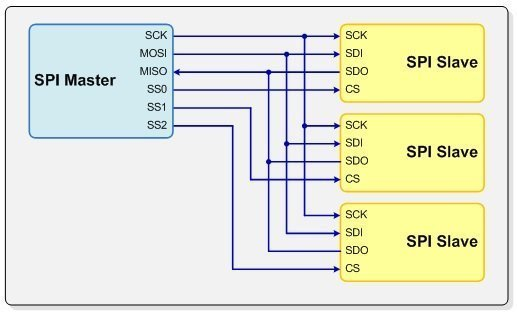
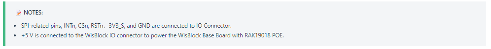
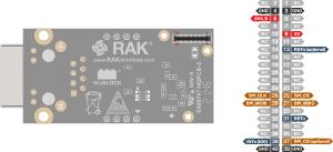
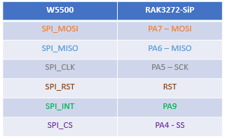
As first analyzing step i kindly ask for an hint about the wiring. Currently I’ve just connected 4 SPI wires, is it correct? Have I to connect, and how, other wires ?

Info: the led on the eth plug and on the switch are on and blinking.

Thanks a lot.

The skecth:

/**
   @file RAK13800_Ethernet_DHCP_W5100S.ino
   @author rakwireless.com
   @brief  Get an IP address via DHCP and print the address obtained.
   @version 0.1
   @date 2021-11-02
   @copyright Copyright (c) 2021
**/

#include <SPI.h>
#include <RAK13800_W5100S.h> // Click to install library: http://librarymanager/All#RAK13800_W5100S

byte mac[] = {0xDE, 0xAD, 0xBE, 0xEF, 0xFE, 0xED }; // Set the MAC address, do not repeat in a network.

void setup() 
{
  time_t timeout = millis();
  // Initialize Serial for debug output.
  Serial.begin(115200);
  while (!Serial)
  {
    if ((millis() - timeout) < 5000)
    {
      delay(100);
    }
    else
    {
      break;
    }
  }
  Serial.println("RAK13800 Ethernet DHCP example.");
  Ethernet.init( PA4 );

  Serial.println("Initialize Ethernet with DHCP.");   // start the Ethernet connection.

  if (Ethernet.begin(mac) == 0) 
  {
    Serial.println("Failed to configure Ethernet using DHCP");
    if (Ethernet.hardwareStatus() == EthernetNoHardware)  // Check for Ethernet hardware present.
    {
      Serial.println("Ethernet shield was not found.  Sorry, can't run without hardware. :(");
      while (true) 
      {
        delay(1); // Do nothing, just love you.
      }
    }
    while (Ethernet.linkStatus() == LinkOFF) 
    {
      Serial.println("Ethernet cable is not connected.");
      delay(500);
    }
  }
  
  Serial.print("My IP address: ");
  Serial.println(Ethernet.localIP()); // Print your local IP address.
}

void loop() 
{
  //  Add your code here.
}

Output without eth module:

RAK13800 Ethernet DHCP example.
Initialize Ethernet with DHCP.
Failed to configure Ethernet using DHCP
Ethernet shield was not found. Sorry, can't run without hardware. :(

Output with the module

RAK13800 Ethernet DHCP example.
Initialize Ethernet with DHCP.

@beegee sent to me a spreadsheet to check if you have a pin configuration conflict: IO map pins

Try to verify if you have any kind of pin configuration conflict.

Regards,

Cláudio

@crmrosa I’m sorry but i don’t understand your post.

I’m not using wisblock hardware but i’m building a my own custom module and i need to know how i have to wire the RAK3272-SiP and the W5500 ethernet module (SPI bus) to let the library able to drive the ethernet module.

Datasheet of the RAK3272-SiP document the 4 SPI pins but the questions is: do the library need other pins? if yes how to wire them ?
Thanks

Your are correct the spreadsheet is only for Wisblock, but the symptom that you are describing could be caused by a PIN assign conflict. I mean, more than one peripheral assign to the same micro-controller PIN, like the figure below, when you have many devices slaves(peripherals), but each one with his own CS connection, and one Master

Cláudio

image

Now i understand your hint, thanks, but, as you can see in the wiring schema that I’ve posted i’ve built a specific minimal module with only RAK3272-SiP and the W5500 module.

RUI3 is the latest 4.1.0 and I’ve installed the RAK13800_W5100S library using library manager of the arduino IDE.

I’ve added some “serial.println” in the w5100.cpp source and i can see that it hang during chip type detection:

RAK13800 Ethernet DHCP example.
Initialize Ethernet with DHCP.
Ethernet begin
w5100 init 0
w5100 init
w5100.cpp: detect W5200 chip
Wiznet soft reset

Reading the wisblock IO sheet it seem that there are other pins:

  • RST
  • IRQ
    but i’m not able to understand what cpu pin they have to be connected to.

Using the xls we can see that for the eth module 6 pins are used:
image

But… what are the RAK3272-SiP pins for IO3 (RST) and IO6 (INT) ?
Thanks

Take a look in the your board documentation, it has the PIN map configuration: RAK3272-SiP Breakout Board Datasheet #Overview

Hi, I’m aware of the docs site and I’ve read it a lot before posting.

As you can see, in the RAk3272-SiP hardware documents:

the IO3 and IO6 labels are not present.
Same situation looking at the schematic.

Maybe that i’m no smart, but i think that the question remain:
The eth library, what pins needs to use on a RAK3272-SiP module (pls using label that can be found in the docs) ?

Waiting for the info from eth experts I’ve done a little deep dive into the code (i’m not an expert so i can be completely wrong):
int the variant.h file stored in
Arduino15\packages\rak_rui\hardware\stm32\4.1.0\variants\WisDuo_RAK3272-SiP_Board
I’ve found this definitions:

/*
 * WisBlock Base GPIO definitions
 */

#define WB_IO1                 PB5          // SLOT_A SLOT_B
#define WB_IO2                 PA8          // SLOT_A SLOT_B
#define WB_IO3                 PB12         // SLOT_C
#define WB_IO4                 PB2          // SLOT_C
#define WB_IO5                 PA15         // SLOT_D
#define WB_IO6                 PA9          // SLOT_D
#define WB_IO7                 PA10
#define WB_SW1                 0xFF         // IO_SLOT
#define WB_A0                  PB3          // IO_SLOT
#define WB_A1                  PB4          // IO_SLOT
#define WB_I2C1_SDA            PA11         // SENSOR_SLOT IO_SLOT
#define WB_I2C1_SCL            PA12         // SENSOR_SLOT IO_SLOT
#define WB_I2C2_SDA            PA10         // IO_SLOT
#define WB_I2C2_SCL            PA9          // IO_SLOT
#define WB_SPI_CS              PA4          // IO_SLOT
#define WB_SPI_CLK             PA5          // IO_SLOT
#define WB_SPI_MISO            PA6          // IO_SLOT
#define WB_SPI_MOSI            PA7          // IO_SLOT
#define WB_RXD0                PB7          // IO_SLOT
#define WB_TXD0                PB6          // IO_SLOT
#define WB_RXD1                PA3          // SLOT_A IO_SLOT
#define WB_TXD1                PA2          // SLOT_A IO_SLOT

Is it correct to assume that

IO3 -> PB12
IO6 -> PA9

and that PB12/PA9 are the pins that the eth library needs ?

Thanks

Pin numbers like WB_xx are from WisBlock modules.
In your case you have to connect the matching pins from the W5500 to the corresponding pins on the SIP module.

As our WisBlock module is using the W5100, pin numbers on the W5500 might be different.
And there might be more pins needed, I do not know.
On the W5100/RAK13800 you need only RSTn, INTn, MISO, MOSI, SCLK and CSn

Pins on our RAK13800 Ethernet module with W5100:

Pins on the RAK3172-SiP breakout board:

Good morning,

@beegee is the guy!

Just to try to help, take a look in the hardware description section in the board documentation: RAK13800 WisBlock Ethernet Module Datasheet

Here below you will see exactly what @beegee described in the his post:

image

@beegee Thanks a lot for your detailed info.
I’ll try asap and post a feedback.

@crmrosa Thanks you too.

Hi all, as promised, I post first test result.

Status
No good news, the code seems to hang and I’m not able to analyze further in the next days.

Next action (hints welcomes)
Buy a W5100s module to repeat the test using it (I’m not so confident because the library should support W5500 but I’ve no other idea to go on)

Details
I’ve build a specific test system using breadboard (not so good to show but pls be patient :-)):

This is the wiring:
image

I’ve flashed the RAK3272 module using the sample skecth compiled using arduino IDE:

/**
   @file RAK13800_Ethernet_DHCP_W5100S.ino
   @author rakwireless.com
   @brief  Get an IP address via DHCP and print the address obtained.
   @version 0.1
   @date 2021-11-02
   @copyright Copyright (c) 2021
**/

#include <SPI.h>
#include <RAK13800_W5100S.h> // Click to install library: http://librarymanager/All#RAK13800_W5100S

byte mac[] = {0xDE, 0xAD, 0xBE, 0xEF, 0xFE, 0xED }; // Set the MAC address, do not repeat in a network.

void setup() 
{
  time_t timeout = millis();
  // Initialize Serial for debug output.
  Serial.begin(115200);
  while (!Serial)
  {
    if ((millis() - timeout) < 5000)
    {
      delay(100);
    }
    else
    {
      break;
    }
  }
  Serial.println("RAK13800 Ethernet DHCP example.");
  Ethernet.init( PA4 );

  Serial.println("Initialize Ethernet with DHCP.");   // start the Ethernet connection.

  if (Ethernet.begin(mac) == 0) 
  {
    Serial.println("Failed to configure Ethernet using DHCP");
    if (Ethernet.hardwareStatus() == EthernetNoHardware)  // Check for Ethernet hardware present.
    {
      Serial.println("Ethernet shield was not found.  Sorry, can't run without hardware. :(");
      while (true) 
      {
        delay(1); // Do nothing, just love you.
      }
    }
    while (Ethernet.linkStatus() == LinkOFF) 
    {
      Serial.println("Ethernet cable is not connected.");
      delay(500);
    }
  }
  
  Serial.print("My IP address: ");
  Serial.println(Ethernet.localIP()); // Print your local IP address.
}

void loop() 
{
  //  Add your code here.
}

And i’ve added some other “serial.print” in the w5100.c module (here just a fragment useful for further comment):

uint8_t W5100Class::isW5200(void)
{
chip = 52;
Serial.println("w5100.cpp: detect W5200 chip 0");
if (!softReset()) return 0;
Serial.println("w5100.cpp: detect W5200 chip 1");
writeMR(0x08);
if (readMR() != 0x08) return 0;
Serial.println("w5100.cpp: detect W5200 chip 2");
writeMR(0x10);
if (readMR() != 0x10) return 0;
Serial.println("w5100.cpp: detect W5200 chip 3");
writeMR(0x00);
if (readMR() != 0x00) return 0;
Serial.println("w5100.cpp: detect W5200 chip 4");
int ver = readVERSIONR_W5200();
//Serial.print("version=");
Serial.println(ver);
if (ver != 3) return 0;
Serial.println("chip is W5200");
return 1;
}

// Soft reset the Wiznet chip, by writing to its MR register reset bit
uint8_t W5100Class::softReset(void)
{
	uint16_t count=0;

	Serial.println("Wiznet soft reset");
	// write to reset bit
	writeMR(0x80);
	Serial.println("Wiznet soft reset writeMR");
	// then wait for soft reset to complete
	do {
		uint8_t mr = readMR();
		//Serial.print("mr=");
		Serial.println(mr, HEX);
		if (mr == 0 || mr==0x03) return 1;
		delay(1);
	} while (++count < 20);
	return 0;
}

Running the code with eth module powered off the Ethernet shield was not found. message is correctly issued.

Running with the eth module powered on the code hangs:

RAK13800 Ethernet DHCP example.
Initialize Ethernet with DHCP.
Ethernet begin
w5100 init 0
w5100 init
w5100.cpp: detect W5200 chip 0
Wiznet soft reset

It seems to hang in the
writeMR(0x80);
instruction.

The board selected is:
image

and the library is:
image