I’m testing RAK4260 chip with the evaluation board and can’t update the firmware.
I’m using windows 10 64bit, and I have tried several jflash versions, but when connecting the RAK board to the computer by USB and selecting the connect jflash menu option I always get the same error “no USB emulator found” and jflash ask me to connect by and IP address.
RAK serial monitor connects to the RAK4260 board without problems and the device is always recognised as usb serial port by windows.
Is there any other step am I missing.
I don’t know how t connect the reset interface using a micro usb cable.
I the documentation (https://doc.rakwireless.com/rak4260-wisduo-lora-module/burning-the-firmware) says install jlink flash software, plug rak4260 board to the pc with a micro usb cable and click connect from j-flash. This doesn’t work because j-Flash does no recognise rak4260 connected by usb as a j-link device.
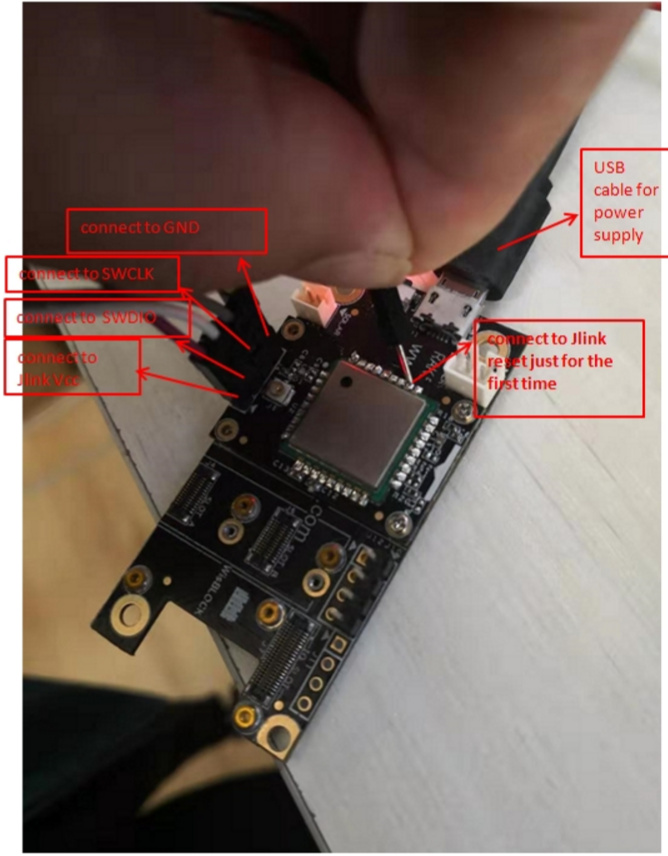
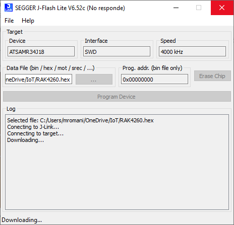
I’m trying to do it using a j-link device connected to the pc by usb and to the rak4260 with 4 wires 3.3v, gnd, SWDIO and SWCLK . I can then connect to j-link emulator and to the target board but when I try to burn the firmware it hangs as you can see in the following screenshot.
Do I have to connect the jlink reset pin to any other pin in the rak4260 board?
First, the MCU is sometimes referred as a SAMR34J18 and sometimes as SAML21J18. Now I know SAML21J18 is inside SAMR34J18 but at the beginning sounds like there is something wrong when having problems burning the firmware. This is not a big problem just confusing.
Second, the documentation guide you through the process of burning the firmware connecting the RAK5005 usb to the computer running j-flas but j-flash never recognise the RAK5005 board as a jlink device capable to communicate with the RAK4260. I finally had to connect the RAK4260 to j-link using the swd interface (vtref, gnd, swclk and swdio) and the j-link device to the pc.
Now I can modify the firmware compile and burn it without problems.
And the last point is just a question about the antenna, I use the EU (868) frequency plan but don’t know if the antenna that comes with the board works in this frequency.
I just received the RAK4260 evb and now I found out usb doesn’t work directly to program the board
I thought from the docs that it was possible so I didn’t purchase a jlink programmer
unfortunately now i have to wait more time to purchase a jlink
wished it was more clear in the docs
Hi @Nicholas
So the USB is only used to power the wisduo?
are the pins PA24_USB_N and PA24_USB_P of the RAK4260 Connected to RAK5005 USB port?
is the https://downloads.rakwireless.com/en/LoRa/RAK4260/Hardware-Specification/RAK4260_EVB_Schematic.pdf the same schematic for the wisduo that is send with the evb? cause in the Schematics J4 is the antenna while on the actual board J4 is a header and J6 is the antenna , and more components exit on the actual board
So the TTL can be used used for programming ? Software to be used?
What pins are used to connect the TTL serial port?
if so It would be nice to include a fdti chip in the RAK5005 in future versions
Where to find the Pinout For the RAK5005?
Mike
From your answer it looks like there is another way to program the RAK4260 when installed in a RAK5005. Are you suggesting to use a TTL programmer rather than the J-Link programmer. If so, can you describe the pin connections on the RAK5005 board for the TTL connections.
By the way, the instructions at RAKwireless Documentation Center would never work. Even in this documentation there are error message in Figure 12 and Figure 13

 and will fix this in guide asap. Yes antenna will work.