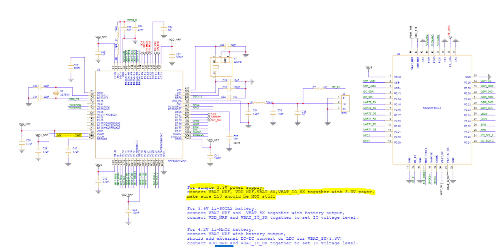
Hi I am designing a small IoT PCB with RAK4630 and i see that in the schematic it says that L10 has to be removed to run the module of single 3.3V power supply.
Does anyone know how to do this, as I think L10 is inside the module shield can?
Has anyone used this module with a single 3.3V power supply?
If yes, what sort of sleep current did you achieve?
I find the sleep current is too high and i doubt if it is down to this, so any help is much appreciated.
What power consumption are you getting?
What firmware are you using?
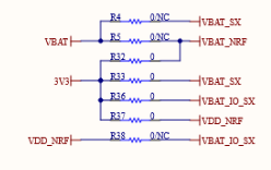
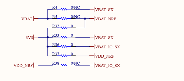
The information in the schematic is outdated. On our RAK10702 Indoor Air Quality device we are using the RAK4630 with a single power supply of 3.3V using this power pin connections:
Edit ==> Comment
The schematics are not outdated. We are using a variant of the RAK4630 that is changed to run with a single supply voltage!.
With all sensors removed, running a Low-Power-PIO example code, I am getting an average sleep current of 35uA. This is an expected value with the LoRa transceiver active and the device connected to a LoRaWAN server.
The sleep current measured on a RAK4631 (tested standalone, not with a Raspberry PI) was 170uA (also running with a single 3.3V power supply)
We have the same power supply configuration on our hardware as what you showed where all the supply pins are connected to a single 3.3V power supply.
The link you gave is just the library, not a specific code (example).
I am getting the best results for power consumption when I avoid using the loop and make my code event based, leaving the MCU in low power whenever possible.
I am doing this using timers, FreeRTOS semaphores and queues and external interrupts.
The Low Power Pio example I linked is using this practice by implementing the WisBlock-API-V2
The information in the schematic is outdated. On our RAK10702 Indoor Air Quality device we are using the RAK4630 with a single power supply of 3.3V using this power pin connections:
So @beegee@carlrowan you confirm that powering and wiring RAK4630 as follow is ok?
VBAT_SX => 3.3V
VBAT_IO_SX => 3.3V
VBAT_NRF => 3.3V
VDD_NRF => 3.3V
Here is my original question for reference and looks like VDD_NRF should ne not connected, so sorry but all is confusing.
I dont know why but connecting all supplies of the RAK4630 to a single 3.3V results in either higher sleep current or a system collapse on startup.
My system is powered by a 3.6V battery, so i followed what the RAK4630 schematic says and connected VBAT_NRF and VBAT_SX to 3.6V & NDD_NRF and VDD_IO_SX to 3.3V.
Now that i have done it, the system comes up reliably and is stable. I did a quick measurement of sleep current and is inline with what i was hoping.
thanks, interesting so you’re between 2uA to 5uA in sleep mode?
I dont know why but connecting all supplies of the RAK4630 to a single 3.3V results in either higher sleep current or a system collapse on startup.
our first batch is using this all tied together, I’ll see, and I will try to remove cover and then L10 to see if it is changing things.
This is the power supply connections we use on our RAK10702 with a single 3.3V supply
Got it thanks @beegee, my concern is about your 35uA sleep mode with this configuration, I’m expecting something about 4uA (with SX in sleep mode of course), we currently use RAK3172-SIP with 1.5uA sleep mode.
The lowest we measured (one off measurement) was ~11uA. We will have to redo measurements properly once we solve other issues. Our target is ~25uA, but obviously we will be happy to have lower sleep currents
Please let me know what you see with your hardware.
For sure, now we are waiting for our current custom board. I can’t go further right now because on stand alone RAK4631 module with 5 pins headers has 3V3 but it does not wire to VDD_NRF and VBAT_NRF so FW is not starting
I may try to wire 3V3 soldering R4 and R7 but I may loose damage something if I plug back on WisBlock base
And putting RAK4631 it on wisblock plate add too much things so I can’t really measure consumption.
Just FYI, We did measure sleep current on RAK4631 running on a Wisblock base board using a nordic PPK2. We measured an average of 24uA.
From what i can see, the RAK4631 has VBAT_NRF wired to a higher voltage than the 3.3V when plugged into the wisblock base board. I tried to emulate this config on my hardware by connecting just the VBAT_NRF to 3.6V while all other VCC pins (VBAT_SX, VBAT_IO_SX and VDD_NRF) are connected to 3.3V. The RAK4630 module didnt come up and looked like it was resetting during power up (like a brownout reset)
yeah this why I really want to try with only RAK4631 modules,
BTW using 1st LDO of the NRF (VBAT_NRF) need also a soft conf to enable it or not, this SOC is really awesome with plenty of options to power, but need fine tuning (hard and soft side) but I really want to get rid of this LDO to avoid any more qescient current.
Reading datasheet you even should be able to power the whole with 3.6V without any on board LDO. Both NRF and SX chip works up to 3.6V
By the way would you able to share your sample code if it is for zephyr+nrf connect?
@e1uk if you check the documentation RUI there is something interesting
WARNING
VBAT should be higher than 3.3 V. The recommended value is the nominal voltage of a Li-Ion battery, which ranges from 3.7 V to 4.2 V. This is required because the power configuration of the nRF52840 inside the RAK4630 is High Voltage, DC/DC with REG0 and REG1 enabled.
And in our case this is exactly what we don’t want (REG0 enabled) because we don’t need it and we don’t want it to be activated and thus consuming current. The configuration we need is the following
So does the warning apply when writing code for Arduino RUI3 or for all configurations?
Anyway in our use case single supply from (3V to 3.6V), for best power optimization we need to remove all LDO we can, I think we could leave VDDH (VBAT_NRF) unpopulated, leave L10 and connect 3.3V to VDD and disable REG0
Could anyone at RAK @carlrowan@beegee could confirm this option to work (and as stated in another thread, option to disconnect L10 with solder pad would be awesome)
This single supply voltage connection:
is used in two of our devices, the RAK2560 and the RAK10702
but
The RAK4630 used in these devices have the L10 REMOVED. They are different to the WisDuo and WisBlock Core modules we are selling in the store.
All WisDuo RAK4630 and WisBlock Core RAK4631 modules sold to customers have the L10 assembled. So if you use single supply to VBAT_NRF (connected to VDDH of nRF52) and VDD_NRF (connected to VDD of nRF52) there might be a higher power consumption. (Still trying to find out what will happen in this case).
@beegee interesting, thanks, would you be able to do same test (VBAT_NRF connected to VDD_NRF) with L10 populated, but disabling REG0 DC/DC (thus letting just LDO or even disable LDO) by software may be it should solve the issue
nRF52840 has 4 supply options:
(1) Normal voltage with LDO
(2) Normal voltage with DCDC
This uses only REG1
(3) High voltage with LDO
(4) High voltage with DCDC
This uses REG0 and REG1
The “standard” RAK4630/RAK4631 uses (4), High voltage with DCDC. In this mode both DCDC are enabled, and it requires the two supply voltages (more about that below)
In the modified version without L10, the RAK4630/RAK4631 is (2), still using the DCDC, but only one of them.
Using (2) with the L10 mounted cost you ~5uA of higher power consumption (not tested by me, the value comes from our hardware guy)
Now about the two voltage supply requirements.
In the “standard” RAK4630/RAK4631 VBAT_NRF is supplying the DCDC in the nRF52830 and the 3V3 is supplying the SX1262 with VBAT_SX and VBAT_IO_SX.
Looking into the SX1262 datasheet, the SX1262 is accepting between 1.8 and 3.7V supply voltage. So you cannot connect it directly to a Li-Ion battery (4.2V). But it is no problem to connect to 3V from a AA battery or similar.
We tested 4 units for sleep current yesterday. The wiring configuration was 3.6V to VBAT_NRF and VBAT_SX and a unregulated diode drop (~3.3V) to VDD_NRF and VBAT_SX_IO.
We measured ~20uA on 2 units and about 200uA on the other 2 units.
To make things worse, i couldnt get my hardware to run stably at a single supply of 3.3V.
This is all confusing but unfortunately we have many other issues to solve so will look into this in a couple of weeks and will update what i find. Worst case we might have to ditch the RAK module and design using discrete ICs ourselves…
Hi @beegee What about VDD_NRF? Can we leave this unconnected and use the internally generated voltage from VBAT_NRF?
I would say absolutely yes if 3.6V going to VBAT_NRF just connect output VDD_NRF to VBAT_IO_SX
Anyway as I wrote earlier there is also a software side to enable/disable REG0 and if it is enabled configuring if it works in LDO or DC/DC mode. I need to find out where to do this setup (like in fuses of NRF or by software on startup)
I’m pretty sure disabling REG0 (1st stage regulator) will solve issue in our case
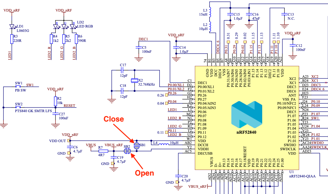
Just made some test on basic board, decided to test with NRF52840 Dongle (official from nordic PCA100059) because this is the most minimal board I’ve found
I closed SB1 opened SB2 and of course removed from USB and powered with 3.3V on VDD_nRF (so connect 3.3V on VDD also) As you can see L4 (L10 RAK board) is there, Nordic say nothing about this one so from my point of view leaving it is not an issue.
And guess what, zephyr sample sleep (power off mode) give me datasheet expected value 450nA
I tried to disable/enable REG0/REG1 and guess what, values are the same, so I’m wondering if NRF is so smart that it adjust itself best REGx values.